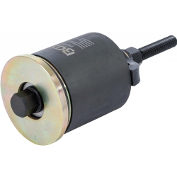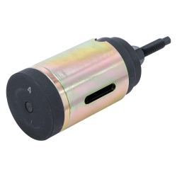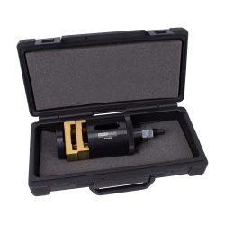
Front Control Arm Bush Tool Set for MINI One, Cooper & Cooper S R50 R53
-
Code:8842
-
Weight:3.183 Kgs
Overview:
✔ Professional tool set for removing and installing front control arm bushes
✔ Suitable for MINI One, Cooper and Cooper S models
✔ Compatible with R50 and R53 chassis vehicles
✔ Allows bush replacement directly on the vehicle without removing the control arm
✔ Used as BMW OE 31126757551
✔ Includes spindle, bearing, sleeve and pressure adapters
✔ Suitable for professional workshop repairs


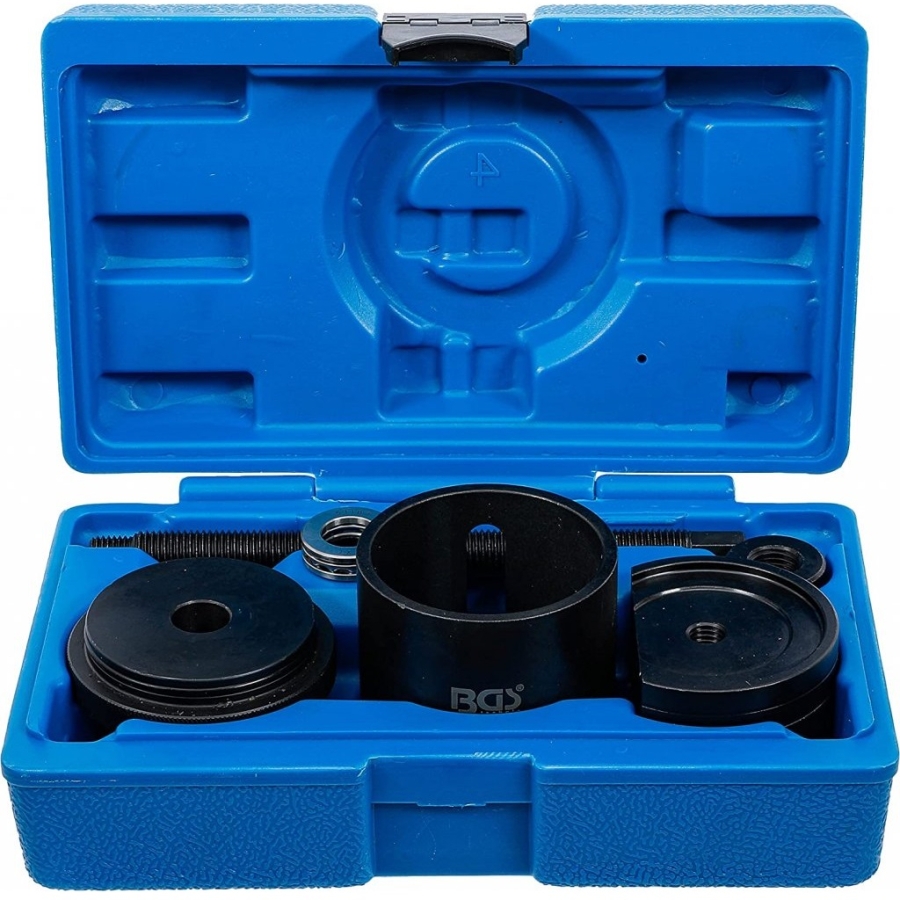
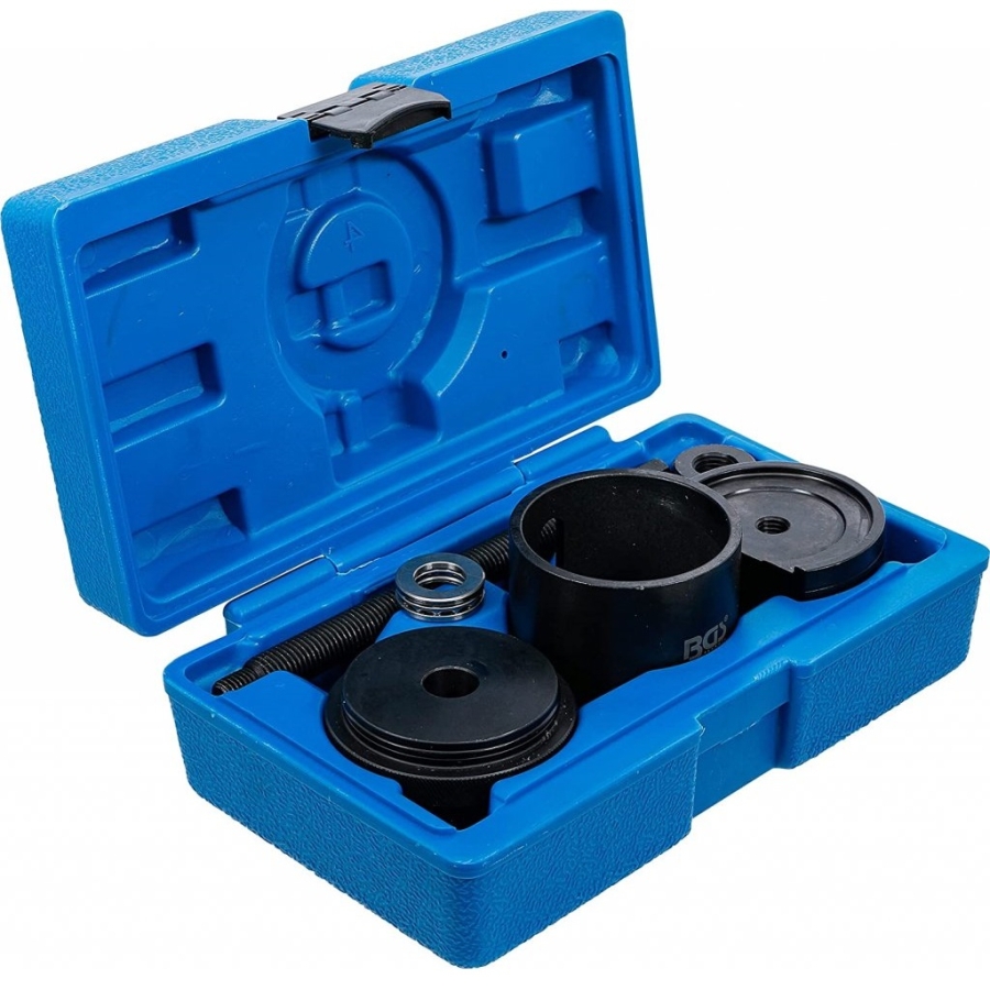
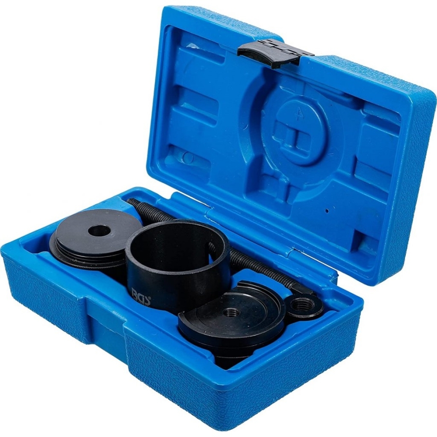
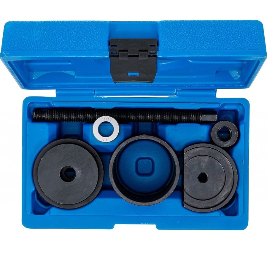
This specialist tool set is designed for the removal and installation of front control arm bushes on MINI vehicles. The tool allows the bushes to be serviced directly on the vehicle without removing the control arm, helping reduce repair time and simplifying suspension maintenance.
The precision-fit components ensure controlled installation and removal while minimizing the risk of damage to surrounding suspension components.
Vehicle Compatibility
Suitable for:
- MINI One (2001>)
- MINI Cooper (2001>)
- MINI Cooper S (2001>)
Chassis codes:
- R50
- R53
Engine families:
- W10
- W11
- W17
OEM Reference
The included tools are used as:
- BMW OE 31126757551
Technical Specifications
Spindles:
- M16 × 2
- M12 × 1.75
Spindle nut:
- M16
Drive:
- 24 mm external hex
Bearing:
- Ball bearing 51103
Sleeve:
- Internal diameter: 67 mm
- External diameter: 79 mm
- Length: 75 mm
Washer:
- Internal diameter: 17 mm
- External diameter: 78 mm
Flattened pressure plate:
- Internal thread: M12 × 1.75
- External diameter: 77 mm
Flattened pressure plate:
- Internal diameter: 68 mm
- External diameter: 77 mm
Pressure plate:
- Internal thread: M12 × 1.75
- External diameter: 65 mm
Package Contents
- 1 × Spindle M16 × 2
- 1 × Spindle M12 × 1.75
- 1 × M16 spindle nut
- 1 × Ball bearing 51103
- 1 × Installation sleeve
- 1 × Washer
- 3 × Pressure plates
Direct On-Vehicle Service
The tool set is specifically designed to replace front control arm bushes without removing the control arm from the vehicle. This significantly reduces labor time and makes suspension repairs more efficient.
Original part and tool numbers are provided for reference and comparison purposes only. This product is not an original BMW or MINI tool.
Application & Maintenance
- Lubricate the spindle and spindle nut before and after each use.
- Do not use pneumatic or impact tools to drive the spindle or spindle nut.
- The maximum spindle load is 150 Nm. Exceeding this torque limit will significantly reduce the service life of the spindle.
- The spindle and spindle nut are considered wear components and are not covered by warranty.
General Notes
- Always follow the vehicle manufacturer's repair and service instructions when removing or installing bushings.
- Installed bushings may be secured with special adhesive compounds and can be difficult to remove. Do not exceed a spindle torque of 150 Nm during removal.
- If greater force is required, use the tool in combination with a hydraulic press.
- The tool is designed to install the bushing to the correct depth. Before installation, consult the vehicle manufacturer's specifications and ensure the bushing is correctly aligned and positioned.
Important Information
This tool is designed for the removal and installation of suspension bushings. Please observe the following:
- Thoroughly clean the area surrounding the bushing before beginning work.
- Keep the spindle properly lubricated before and during operation.
- Do not use an impact wrench with this tool.
- Stripped threads and bent pressure cups caused by improper use are not covered under warranty.
Bushing Removal Procedure
Step 1 – Assemble the Removal Tool
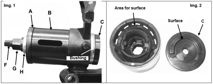
- Install the removal components (black) as shown in Figure 1.
- Fit pressure washer (C) onto the short threaded end of spindle (F) with the serrated side facing inward.
- Insert spindle (F) through the rear of the bushing.
- Install pressure washer (C) with the recessed side facing the bushing (Figure 2).
- Slide sleeve (B) onto spindle (F).
- Position pressure washer (A) so that the rubber ring sits correctly inside sleeve (B).
- Install bearing (H) and nut (G) onto spindle (F) until both components contact pressure washer (A).
- Verify the alignment of all tool components before proceeding.
Step 2 – Begin Bushing Removal
- Using a 24 mm deep socket or wrench, rotate nut (G) clockwise.
- The bushing will begin to be extracted from the control arm housing.
- Warning: Do not exceed a spindle torque of 150 Nm.
Step 3 – Complete Removal
- Continue turning the spindle until the bushing is completely removed.
- Caution: Once the bushing is released, the tool assembly may become loose and could fall.
Step 4 – Alignment Check
- If excessive resistance is encountered, stop the operation.
- Loosen the spindle and verify that all tool components are correctly aligned before continuing.
Bushing Installation Procedure
Step 1 – Prepare the Housing
- Thoroughly clean the inside of the housing before installing the new bushing.
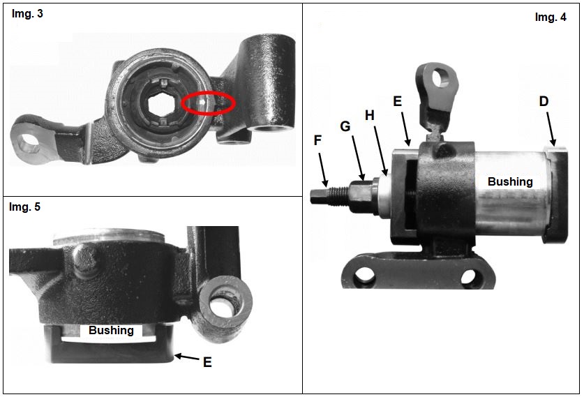
- Ensure that the small arrow on the new bushing is positioned exactly as shown in Figure 3.
- Correct orientation is essential to ensure proper control arm alignment after installation.
Step 2 – Assemble the Installation Tool
- Install the installation components (silver) as shown in Figure 4.
- Fit pressure washer (D) onto the short threaded end of spindle (F) with the serrated side facing inward.
- Slide the new bushing onto spindle (F) and insert it through the control arm.
- Position pressure washer (E) on spindle (F) and seat it against the control arm.
- Install bearing (H) onto spindle (F).
- Thread nut (G) onto the spindle until it contacts pressure washer (E).
- Verify that all tool components are correctly aligned and that the bushing is properly positioned.
Step 3 – Start Installation
- Using a 24 mm deep socket or wrench, rotate nut (G) clockwise.
- The bushing will be drawn into the housing.
- Note: If unexpected resistance occurs, stop immediately and check the alignment of both the tool and the bushing.
Step 4 – Complete Installation
- Continue turning nut (G) until the bushing is fully seated.
- Installation is complete when the bushing contacts pressure washer (E) as shown in Figure 5.
Step 5 – Remove the Tool
- Disassemble the tool.
- Clean and lubricate the spindle threads before storage.
Step 6 – Reinstall the Control Arm
- Reinstall the control arm according to the vehicle manufacturer's repair procedure and torque specifications.