





 Workshop knowledge · Mercedes OM654
Mercedes OM654 balance shafts: position, gear preload and precise installation
When the balance-shaft module is removed, marking its position is not enough. Cylinder 1 TDC, the relative position of both shafts and the spring preload in the split gears must all remain under control. An error of only one or two teeth can mechanically lock the engine.
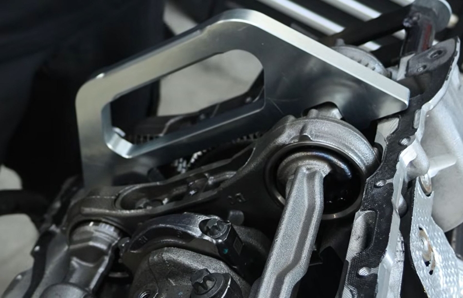
This article explains the workshop logic behind removal, overhaul and refitting of the Mercedes OM654 balance-shaft assembly. The decisive point is that two settings must be managed at the same time: shaft timing relative to the crankshaft and tooth-flank preload inside the split helical gears.
The technical principle
Why the OM654 balance-shaft assembly needs more than timing marks
The two balance shafts are driven through helical gears. Each gear assembly contains two sections that can move relative to one another and are spring-loaded. Their preload compensates tooth-flank backlash, allowing the gears to run without free play.
That construction creates two independent requirements during service. The shafts must return to their prescribed angular position relative to the crankshaft, and the split gears must retain—or, after dismantling, regain—the correct spring preload. Correct timing with released preload is not enough; preserved preload with incorrect shaft timing is equally unsafe.
The crankshaft reference must be established before the balance shafts are locked.
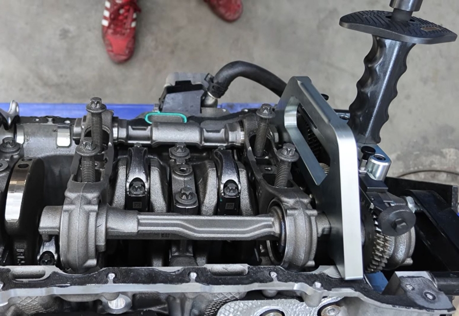
The bridge confirms the shafts' basic position relative to the engine reference.
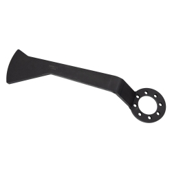
The gear tool controls the spring-loaded sections that eliminate tooth-flank backlash.
Decide before dismantling
Two repair scenarios—and one important difference
The module remains assembled
If the complete balance-shaft assembly is only removed to gain access—for example during work on the crankshaft bearings—the existing shaft position and gear preload can be preserved. Lock both settings before lifting the module and keep the assembly secured until refitting.
Workshop advantage: no unnecessary readjustment of the split gears and a clearly defined installation position.
The module is dismantled or overhauled
If shafts, bearings or gears are separated, the spring-loaded gear sections release and the shafts move away from their defined position. Basic position and preload must then be rebuilt deliberately before installation.
Workshop consequence: previous paint marks no longer describe the internal spring setting.
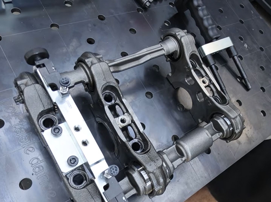
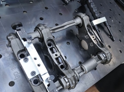
Handle the bearing caps carefully
The bearing caps in the removed assembly have no positive lateral guidance and can shift sideways during handling. Support the complete unit, avoid levering on the gears and check every cap's position before bringing the module back to the crankcase.
Workshop procedure
From the crankcase to the workbench—and back
The following sequence explains the working principle. Vehicle-specific removal steps, tightening torques, angle stages, single-use fasteners and test values must always be taken from the current Mercedes-Benz repair information for the exact engine and vehicle.
Establish the crankshaft reference
Bring cylinder 1 to the prescribed top-dead-centre position. The balance-shaft tool does not create TDC; it verifies and holds the shaft position after the engine reference has been set correctly.
Lock both balance shafts
Fit the positioning bridge without forcing it. A tool that does not seat correctly is a warning to recheck the crankshaft and shaft positions—not an invitation to pull it down with the fasteners.
Secure the split-gear preload
Engage the two teeth of the gear tool precisely in the gear sets and tighten it only as required to hold the setting. The purpose is to retain the spring preload, not to load or distort the gears.
Remove and support the complete assembly
Lift the module evenly from the crankcase while monitoring gear engagement and bearing-cap movement. If it remains assembled, leave the established settings secured for later installation.
If the module has been dismantled: rebuild the gear preload
- Return both balance shafts to the prescribed basic position. In the demonstrated procedure, both shafts point upward; confirm the exact position in the current repair documentation.
- Identify the direction of spring force in each split gear.
- Offset the movable preload section by one tooth on each side so the tool has sufficient adjustment travel.
- Fit the tool into the gear teeth and turn its adjusters until both rows of teeth align again.
- Confirm a full one-tooth preload and keep the setting locked throughout installation.
Guide the bearing cap straight into the crankcase
The crankshaft-bearing fit and the cap-to-crankcase fit are both precise. The dedicated installation tool replaces two bolts at the first crankshaft main bearing and guides the cap squarely into position. Controlled, light impacts through the tool seat the assembly without canting it.
Watch the gear mesh as the assembly enters. With the crankshaft at TDC and the balance shafts correctly locked, the teeth should meet in their prescribed relationship.
Workshop risk control
Common mistakes and what they can cause
| Risk | Possible consequence | Correct control |
|---|---|---|
| Relying only on paint marks | The spring-loaded gear section can move even when an external mark still appears plausible. | Use the defined TDC reference and lock both shaft position and gear preload. |
| Releasing a dismantled module without recording the spring direction | The preload can be rebuilt in the wrong direction or with insufficient travel. | Determine spring force deliberately and follow the current repair method. |
| Installing the bearing cap at an angle | Damage to precision fits, a displaced cap or incorrect gear engagement. | Use the bearing-cap guide and seat the assembly with light, controlled force. |
| Being one or two teeth out | Mechanical interference between the connecting rods and balance shafts; the engine may lock. | Verify tool fit, tooth alignment and free manual rotation before start-up. |
| Using an impact wrench for final assembly | Uncontrolled clamp load and disregard of angle stages or single-use fasteners. | Apply the specified torque/angle sequence with calibrated tools. |
Tool selection
Which tool supports which part of the job?
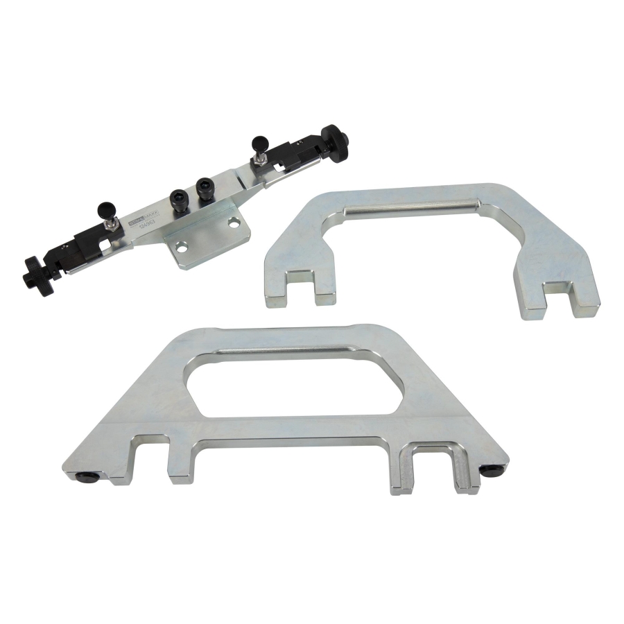
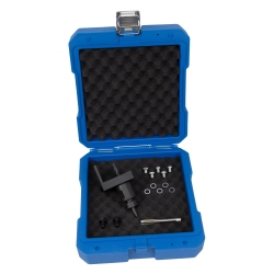
Balance Shaft Basic-Position Tool Set
Positions both balance shafts and controls the spring preload in the split gears during removal and installation.
View the tool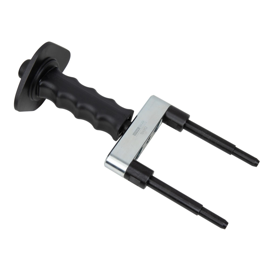
Crankcase Bearing Cap Installation Tool
Guides the bearing cap straight into the close-fitting crankcase position on OM654 and OM656 engines.
View the tool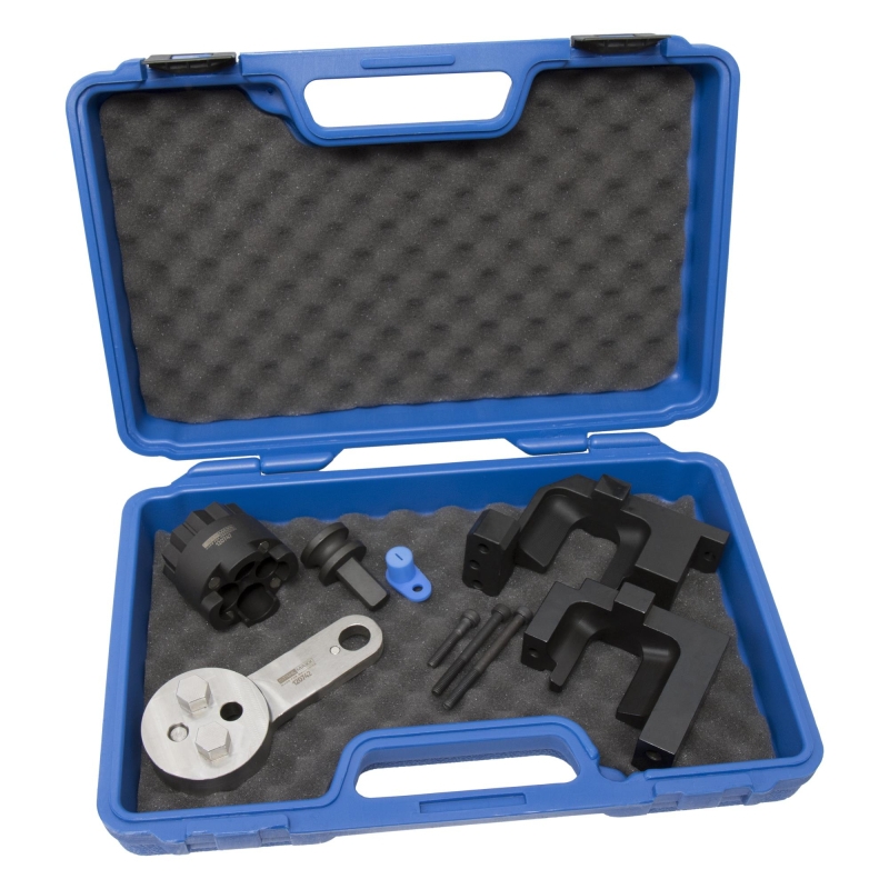
Timing Chain Inspection & Adjustment Set
The recommended timing set for separate work on the timing chain of OM654 and OM656 engines. It is not part of the balance-shaft procedure described here.
View the timing setOriginal numbers are for comparison only; not original tools.
Before first start
A final mechanical check is cheaper than reopening the engine
- Cylinder 1 reference and balance-shaft position rechecked
- Both split gears retain the specified preload
- Bearing caps are seated squarely and in their correct positions
- All fasteners tightened to the prescribed torque and angle
- Gear engagement inspected before removing the setting tools
- Engine rotated manually through the prescribed cycles without a hard stop
Control the setting instead of trying to reproduce it by eye
The dedicated tools turn three difficult variables—TDC relationship, gear preload and bearing-cap alignment—into defined, repeatable workshop steps. That protects the repaired components, reduces rework and provides a much safer route to the first engine rotation.
Explore the OM654 balance-shaft tool

Post comment