





 Workshop knowledge · Broken fasteners
Drilling out broken bolts: how to protect the original thread
A broken bolt rarely leaves a flat, drill-friendly surface. The fracture slopes, access is restricted and a freehand drill naturally wanders. A properly supported guide turns the job into a centred, depth-controlled and repeatable repair.
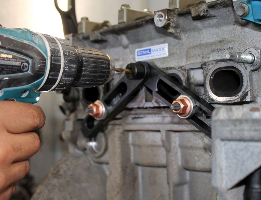
The objective is not simply to remove metal. It is to keep the hole on the fastener axis, stop at a safe depth and leave as much of the original female thread as possible. This guide explains the working method and when to choose a universal M6–M10 guide or the complete low-profile M8/M10 drilling system.
The mechanical problem
The drill follows the easiest path—not necessarily the bolt centre
A fractured fastener normally has a high side, a low side and a hardened, irregular surface. When a drill bit first touches it, one cutting edge engages before the other. The bit is pushed sideways, and that initial error continues deeper into the fastener.
Restricted access makes the problem worse. A hand-held drill that is only slightly angled at the surface can reach the thread wall farther down. Once original thread material has been removed, the job changes from fastener extraction to thread repair—or, in the worst case, component replacement.
Intact holes or studs create a stable reference outside the damaged fastener.
A close-fitting sleeve controls the drill before its cutting edges reach the fracture.
A small pilot bore is enlarged in stages, reducing side load and improving control.
Establishing a reliable reference
One, two or three support points: the component decides
Single-point or butterfly guide
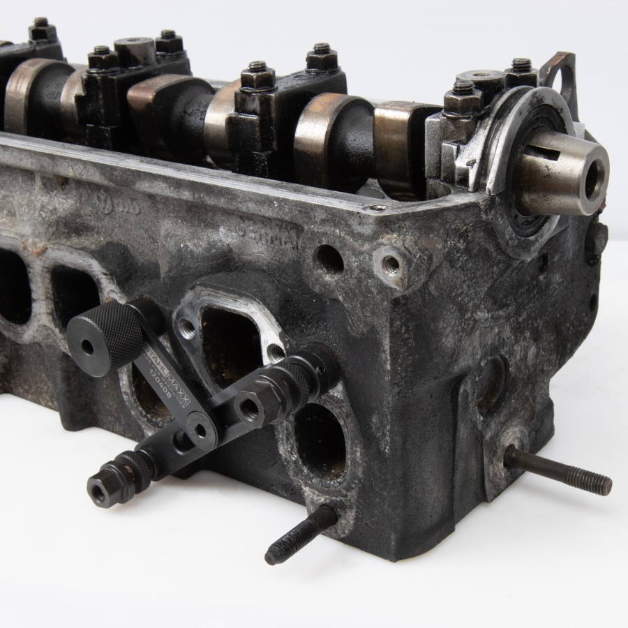
The universal system can be attached to one suitable bolt hole when only one reference is available. Where two mounting points can be used, the adjustable butterfly guide creates a wider and more stable base.
Workshop advantage: the M6, M8 and M10 adapter sleeves and exchangeable drill guides cover changing bolt patterns without resetting the complete job.
Adjustable three-arm guide
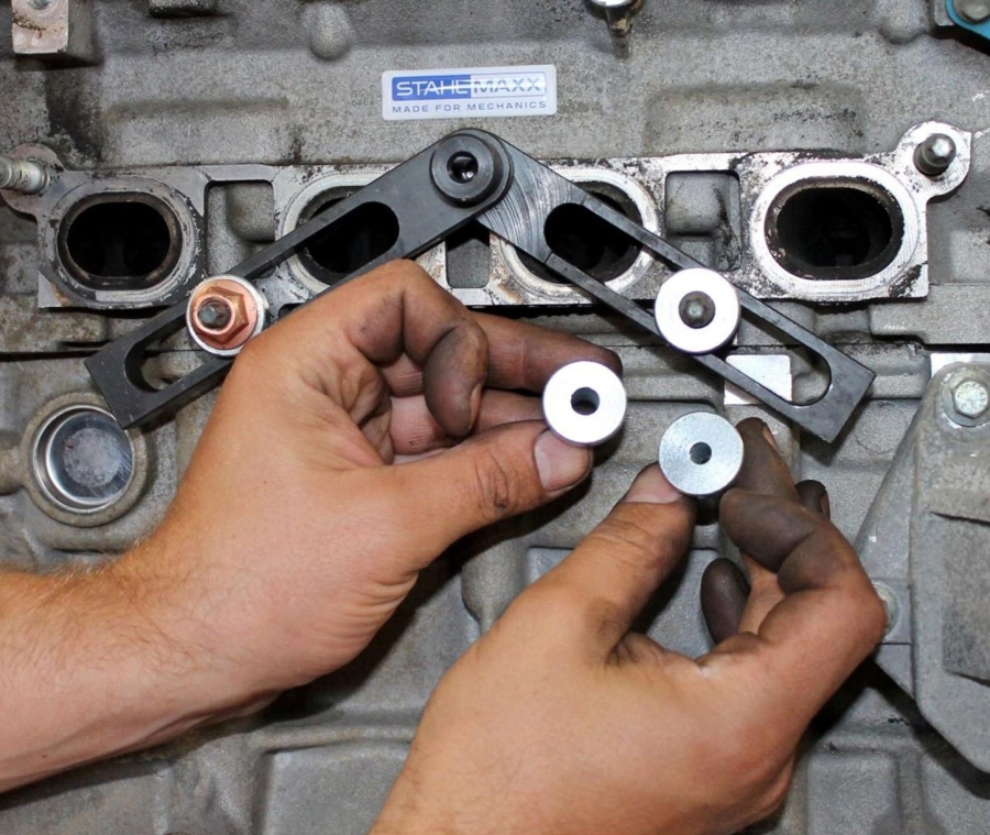
The low-profile M8/M10 system uses surrounding holes or protruding studs to position three adjustable arms. Two-point attachment is recommended wherever the component allows it; the remaining arm carries the drilling guide.
Workshop advantage: the drill bits, guide sleeves and individual depth stops form one controlled drilling sequence.
Alignment must be checked without force
The guide should sit securely while the drill sleeve remains directly above the fastener axis. If the sleeve has to be pulled sideways to reach the fracture, the support points or adapter arrangement must be reconsidered.
Before drilling, look through the sleeve from more than one direction and confirm that the planned bore remains within the fastener core.
Tool selection
Choose by fastener size, mounting pattern and depth-control requirement
| Selection point | Universal guide M6–M10 | Low-profile set M8/M10 |
|---|---|---|
| Fastener sizes | M6, M8 and M10 | M8 × 1.25 and M10 × 1.5 applications |
| Mounting | Single-point jig or adjustable two-point butterfly guide | Adjustable three-arm guide using nearby holes or studs |
| Drill guidance | Guide sleeves for Ø 3, 4.5 and 6 mm drill bits | Guide sleeves and included HSS drills in Ø 4, 6.5 and 8.5 mm |
| Depth control | Depth must be established and controlled by the technician | Individual depth stop supplied for each drill diameter |
| Strongest advantage | Maximum flexibility across different components and mounting patterns | Complete, low-profile process with controlled drilling depth |
The lower profile matters in the engine bay
On cylinder heads, manifolds and turbocharger connections, the theoretical drilling line is often obstructed by the bulkhead, bodywork or installed engine components. The compact three-arm guide is designed to preserve accurate alignment where vertical clearance is limited.
Its depth stops are particularly valuable when the bolt hole ends close to a coolant passage, oil gallery or thin rear wall. They do not, however, replace measuring the component.
Workshop procedure
A controlled sequence from inspection to thread assessment
The following sequence describes the working principle. Always verify the component construction, specified hole depth, required tapping-drill diameter and vehicle manufacturer's repair information before removing material.
Identify the fastener and inspect the fracture
Confirm the thread size, visible fastener diameter and whether the break is above, flush with or below the component surface. Remove loose corrosion and dirt without damaging the surrounding face.
Select sound reference points
Choose intact holes or studs that allow the guide to sit without distortion. Use the correct M6, M8 or M10 adapter components and, wherever possible, establish a stable two-point attachment.
Determine the safe drilling depth
Measure a sound hole or fastener, consult the component data and establish what lies behind the broken bolt. Set the depth stops where the selected system provides them.
Centre and lock the guide
Position the sleeve precisely over the fastener axis, tighten the mounting points evenly and recheck alignment before inserting the drill bit.
Start with the smallest suitable drill
Use appropriate cutting lubricant, a controlled speed and light feed pressure. Withdraw the drill regularly to clear chips and prevent them from packing inside the guide sleeve.
Enlarge progressively and inspect
Move to the next guide diameter only while the bore remains centred. Stop at the measured depth, remove the guide and inspect the remaining fastener wall before proceeding.
What should remain after the core is drilled?
With the bore centred and the correct final diameter selected, a thin shell of fastener material may remain in the female thread. Depending on corrosion and thread condition, this material can often be collapsed and removed carefully with a hook, pick, screwdriver or suitable tap.
- Do not force the tap: first remove loose material and clean out the chips.
- Inspect the full thread: surviving upper turns do not prove that deeper turns are undamaged.
- Repair only after assessment: use a suitable thread-repair method if the original thread no longer provides the required engagement or strength.
A depth stop is a control—not a measurement
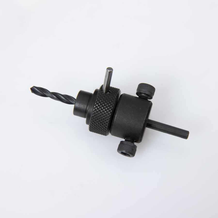
The stop prevents the drill from travelling farther than the setting, but the technician must first establish the correct setting. Check blind-hole depth, rear-wall thickness and nearby passages before drilling.
This is especially important on cylinder heads, engine blocks, gearboxes and thin-wall cast housings, where a few millimetres of excess travel can turn a local repair into major component damage.
Workshop risk control
Common mistakes and what they can cause
| Risk | Possible consequence | Correct control |
|---|---|---|
| Using the fracture surface as the only reference | The drill walks off-centre as soon as one cutting edge engages. | Reference the guide from intact surrounding mounting points. |
| Pulling a misaligned guide into position with its fasteners | The fixture is stressed and the sleeve no longer follows the fastener axis. | Reconfigure the arms, adapters or support points until the guide sits naturally. |
| Starting with the largest drill | Higher side load, more heat and less opportunity to correct the bore. | Create a guided pilot bore and enlarge it step by step. |
| Copying a depth setting from a similar component | Damage to a passage, rear wall or precision surface behind the bolt. | Measure the actual component and verify current repair information. |
| Continuing after the drill begins to bind | Broken drill bit, damaged guide sleeve or an enlarged off-axis bore. | Stop, clear chips, inspect the cutting edges and correct the cause before continuing. |
The two systems
One flexible guide and one complete low-profile drilling set
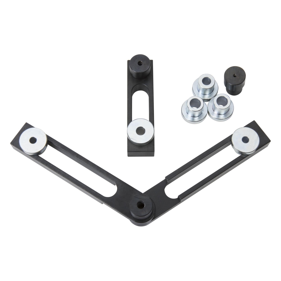
Universal Broken Bolt Drilling Guide Set M6–M10
Single-point and adjustable butterfly mounting options with interchangeable adapters and drill guides for Ø 3, 4.5 and 6 mm.
View the universal guide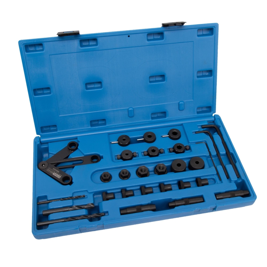
Low-Profile Broken Bolt Drilling Guide Set M8/M10
Adjustable three-arm guide with M8/M10 centring components, HSS drills, guide sleeves and individual depth stops.
View the low-profile setBefore assembly
Inspect the repair before the new fastener goes in
- All chips and loose fastener material removed
- Original thread inspected through its full usable depth
- No drill damage to the component face or rear wall
- Correct thread size and pitch confirmed
- Thread cleaned or repaired using the approved method
- Replacement fastener and tightening data verified
Guide the drill before the fracture guides it
The value of a drilling jig is not simply that it holds a sleeve. It transfers a reliable reference from the intact component to the damaged fastener, allowing the workshop to control centring, drilling stages and depth—and giving the original thread the best possible chance of remaining serviceable.
Compare the broken-bolt guides
Post comment