Automotive Diagnostic Multimeter with Oscilloscope and Signal Generator
-
Code:63407
-
Weight:1.580 Kgs
Overview:
✔ Combines a digital multimeter, oscilloscope and signal generator
✔ Measures AC/DC voltage, AC/DC current, resistance and frequency
✔ Tests starting and charging systems
✔ Supports injector and relay actuation tests
✔ Generates K-line, square-wave and sine-wave signals
✔ Displays ignition, camshaft, crankshaft and wheel-speed sensor signals
✔ Suitable for analysing oxygen-sensor, CAN-bus and K-line data
✔ Large backlit LCD with 240 × 320-pixel resolution
✔ Compact, lightweight and suitable for mobile diagnostics
✔ Update-capable software


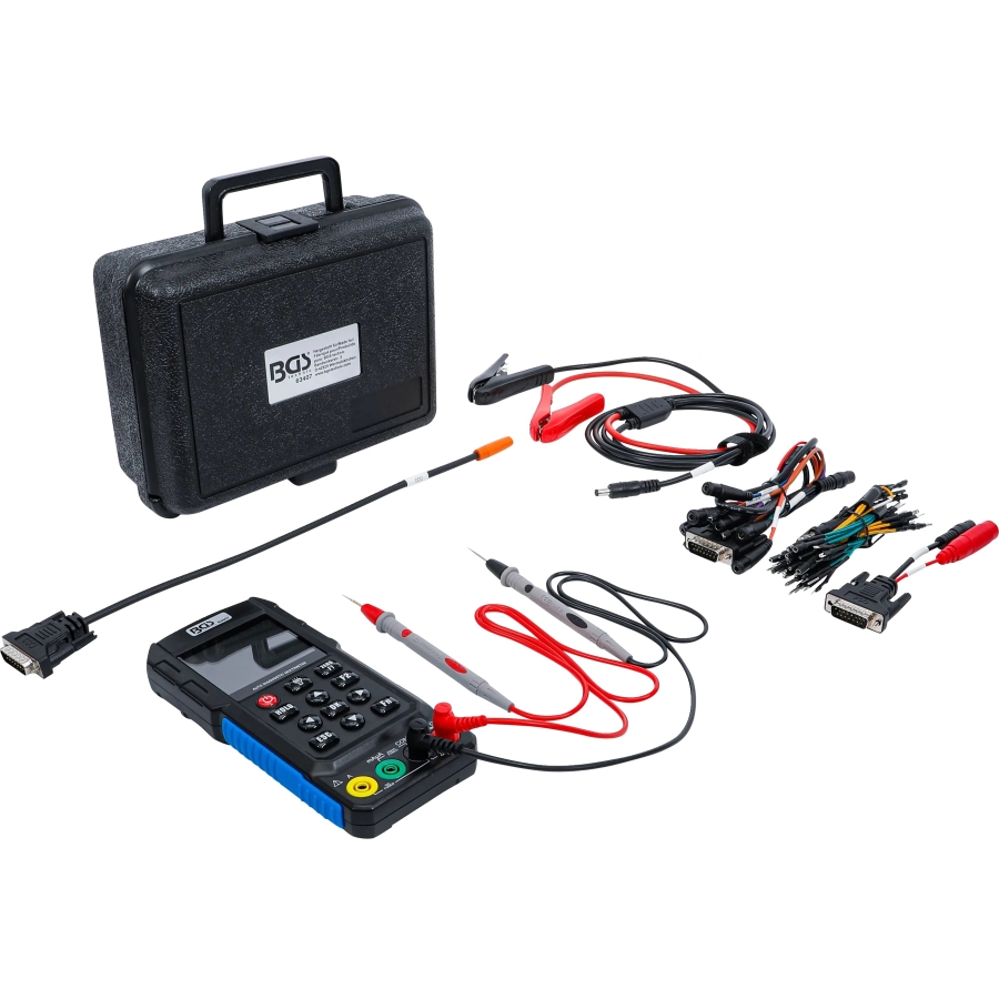
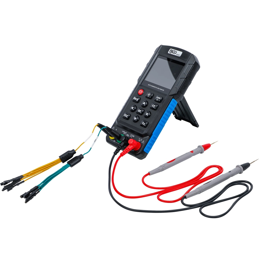
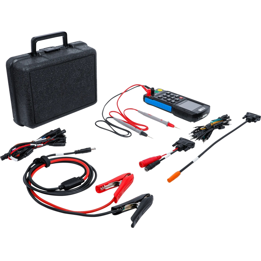
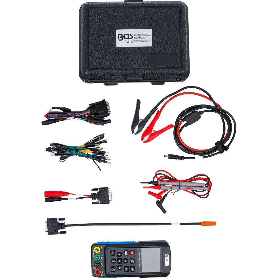
The compact automotive diagnostic tester combines three functions in one device:
- Digital multimeter
- Automotive oscilloscope
- Signal generator
It is designed for electrical measurements, component actuation and real-time signal analysis on vehicle electrical and electronic systems.
Voltage and Current Measurements
The multimeter measures both direct and alternating voltage as well as direct and alternating current.
Voltage measurement specifications:
- Input impedance below 160 V: 2–3 MΩ
- Input impedance above 160 V: 10 MΩ
- Maximum input voltage: 1000 Vpp
- Bandwidth: 500 kHz
Current measurement specifications:
- Measuring range from 0–200 mA, protected by a self-resetting 0.5 A fuse
- Measuring range from 200 mA–20 A, protected by a self-resetting 15 A fuse
- Maximum continuous current measurement: 10 A
- Maximum short-duration current measurement: 20 A
Resistance and Frequency Measurements
Resistance measurement can be used to assess electrical resistors and temperature sensors.
The frequency-measurement function displays pulsating voltage signals in hertz, allowing signal frequency to be checked directly.
Automotive Diagnostic Tests
The device provides dedicated functions for automotive electrical diagnosis:
- Starting-system test: Checks the vehicle starting and charging systems
- Injector test: Actuates an injector and captures its real-time signal
- Relay test: Actuates relays for functional testing
Signal Generator
The integrated signal generator provides several output options for component and circuit testing:
- 5 V K-line square-wave signal
- Selectable baud rates: 1200, 2400, 4800, 9600, 10400, 19200, 38400, 57600 and 115200
- Sine-wave output signal
- Sine-wave voltage range from 0–4.5 V
- Adjustable signal frequency from 1 Hz–10 kHz
- Adjustable duty cycle from 10–90%
Automotive Oscilloscope
The oscilloscope displays real-time waveforms from various vehicle systems and components, including:
- Ignition-pulse signals
- Camshaft-sensor signals
- Crankshaft-sensor signals
- Wheel-speed sensor signals
- Oxygen-sensor signals
- CAN-bus data
- K-line data
Display and Updates
The large backlit LCD provides a resolution of 240 × 320 pixels for viewing measurements, test results and signal waveforms.
The device is update-capable, allowing supported software or firmware updates to be installed.
Scope of Delivery
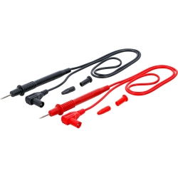
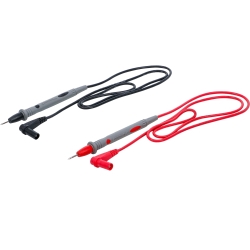
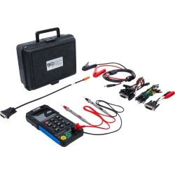
- 1 × automotive diagnostic multimeter
C01 adapter:
- DC connector for connection to the vehicle battery
- Output for injector and relay testing
- K-line and CAN+/CAN− signal connections
- Sine-wave output and 5 V output
- Square-wave output
C03 adapter cable:
- For capturing higher-voltage line signals
C04 adapter cable:
- DC connection for the battery-clamp lead
Technical Specifications
- Functions: digital multimeter, oscilloscope and signal generator
- Voltage measurement: AC and DC
- Current measurement: AC and DC
- Current range: 0 mA–20 A
- Continuous current measurement: up to 10 A
- Short-duration current measurement: up to 20 A
- Maximum input voltage: 1000 Vpp
- Bandwidth: 500 kHz
- Signal frequency: 1 Hz–10 kHz
- Duty cycle: 10–90%
- K-line output: 5 V square wave
- Sine-wave output: 0–4.5 V
- Display: backlit LCD
- Display resolution: 240 × 320 pixels
- Updates: supported
Digital Multimeter
The multimeter supports the following measurements:
- AC and DC voltage
- AC and DC current
- Resistance
- Diode forward-voltage drop
- Continuity testing with an acoustic signal
- Frequency from 1 Hz–1 MHz
The voltage range is selected automatically. The HOLD function freezes the current reading, while the quick-zero function compensates for a non-zero display before measurement.
Automotive Oscilloscope
The integrated 500 kHz oscilloscope uses the standard V and COM inputs and does not require a separate BNC connection.
The following parameters can be adjusted directly:
- Voltage scale
- Time scale
- Trigger level
- Waveform position after freezing the display
Pressing the Fn button during voltage measurement switches directly to the oscilloscope view.
Typical applications include checking signals from:
- Camshaft sensors
- Crankshaft sensors
- Wheel-speed sensors
- Oxygen sensors
- Ignition systems
- Injectors
- CAN-bus and K-line circuits
Automotive Circuit Tester
When connected to the vehicle battery, the circuit-test function displays both the probe voltage and the battery supply voltage.
It can be used to:
- Identify voltage and ground circuits
- Detect possible leakage to ground or supply voltage
- Observe changing signals in oscilloscope mode
- Apply battery positive to a compatible component
- Apply ground to a compatible component
- Function-test lamps and other low-voltage electrical loads
The circuit and component must be identified before applying voltage or ground through the probe.
Starting-System Test
The tester records the minimum battery voltage during engine cranking.
- Minimum voltage above 9.6 V: normal reference range
- Minimum voltage below 9.6 V: possible weak battery, excessive starter current or mechanical resistance
The result should be evaluated together with the battery condition, ambient temperature and vehicle specifications.
Injector Test
The device can actuate a removed electromagnetic injector or capture the operating waveform of an injector installed in the vehicle.
- Adjustable simulation speed
- 3 ms low-voltage drive pulse
- Simultaneous injector actuation and oscilloscope display
- Supports electromagnetic injectors, including compatible GDI injectors
- Allows real-time waveform capture during engine operation
Injectors requiring a high-voltage drive of approximately 120 V may not be fully actuated by the low-voltage test output.
Relay Test
The tester actuates the relay coil using the voltage supplied by the connected vehicle battery. The contact resistance can be monitored simultaneously through the multimeter inputs.
- Use a 12 V battery only with compatible 12 V relays
- Use a 24 V battery only with compatible 24 V relays
- Do not test a relay using a supply voltage different from its rated operating voltage
Ignition-Pulse and Engine-Speed Test
The ignition-pulse sensor is positioned near the ignition lead or ignition coil of one cylinder.
Selectable measurement modes include:
- Distributor ignition
- Two-stroke engines
- Four-stroke engines
The device uses the detected ignition pulses to calculate and display engine speed.
Signal Generator
The integrated signal generator provides several outputs for testing circuits, control units and compatible components:
- Approximately 5 V square-wave signal
- 5 V K-line square-wave signal
- Approximately 5 Vpp sine-wave signal
- Sine-wave output from 0–4.5 V
- 12 V square-wave output when connected to a vehicle battery
The output frequency is adjustable from 1 Hz–10 kHz. The duty cycle of the square-wave signal can be adjusted from 10–90%.
No signal is generated when the function is opened initially. Press OK to start or stop the output.
The generated waveform can be viewed simultaneously with the oscilloscope at frequencies up to 6000 Hz.
K-Line Data
The device can detect data on 5 V and 12 V K-line circuits.
Supported baud rates:
- 1200
- 2400
- 4800
- 9600
- 10400
- 19200
- 38400
- 57600
- 115200
For a standard OBD-II connection, pin 5 is commonly used as signal ground and pin 7 as the K-line. The correct vehicle wiring diagram must always be checked because a vehicle may contain several separate K-lines.
Received data can be frozen, reviewed and cleared directly on the device.
CAN-Bus Data
The CAN+ lead connects to CAN-H, while the CAN− lead connects to CAN-L.
Supported CAN data rates:
- 500 kbit/s
- 250 kbit/s
- 125 kbit/s
- 100 kbit/s
- 83.33 kbit/s
- 50 kbit/s
- 33.33 kbit/s
For a standard OBD-II connection, pin 6 is commonly CAN-H, pin 14 CAN-L and pin 5 signal ground. Always verify the vehicle wiring because multiple CAN networks may be present.
The received data can be frozen, reviewed and cleared from the display.
Frequency Measurement
The frequency-measurement function covers signals from 1 Hz–1 MHz.
For a stable result, the tester must be connected to an active signal source with a signal amplitude above 1 Vpp.
Measurement Connections
Use the appropriate inputs for the selected function:
- V/Ω/Hz input: Voltage, resistance, diode and frequency measurements
- COM input: Common connection for the black test lead
- mA/µA input: Current measurements up to 200 mA
- 10 A input: Current measurements above 200 mA
- DB15 interface: Automotive circuit tests, injector and relay actuation, signal output, K-line and CAN-bus testing
Current measurements must be performed with the tester connected in series with the circuit.
Control Functions
- Power: Switches the tester on or off; holding the button resets the device
- HOLD: Freezes a measurement or waveform
- Arrow buttons: Navigate menus and adjust measurement parameters
- ESC: Returns to the previous menu
- OK: Confirms a selection or starts and stops an output
- Fn: Changes the measurement or display mode
- ZERO/F1 and F2: Function-dependent adjustment and quick-zero controls
- Backlight: Switches the display illumination on or off
The automatic sleep timer can be adjusted from 1–30 minutes. Screen brightness and button sounds can also be configured.
Electrical Safety
The device is designed according to IEC 61010 and specified for:
- Double insulation
- CAT II 1000 V
- CAT III 600 V
- Pollution degree 2
Before use, inspect the test leads and housing for damage. Keep your fingers behind the protective guards on the probes.
Exercise additional caution above 60 V DC or 42 V AC RMS. Never apply voltage directly to a current-measurement input.
Current-Measurement Limits
- 0–200 mA input: protected by a self-resetting 0.5 A fuse
- Higher-current input: protected by a self-resetting 15 A fuse
- Maximum continuous current: 10 A
- Maximum short-duration current: 20 A
The high-current function is intended for automotive diagnosis and must not be used on high-current mains circuits.
Operating Conditions and Updates
- Operating temperature: 0–40 °C
- Maximum operating humidity: 75%
- Maximum operating altitude: 2000 m
- Storage temperature: 10–50 °C
- Maximum storage humidity: 70%
Software and data updates can be installed using a MicroSD card and compatible update files supplied through the distributor.