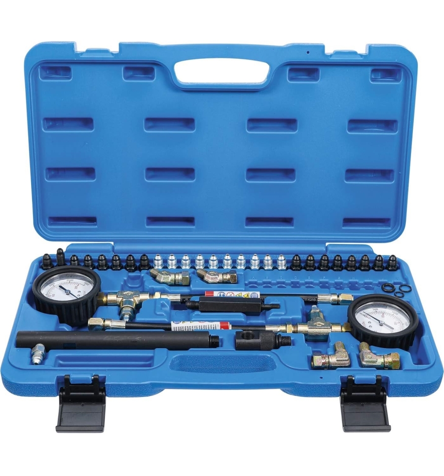
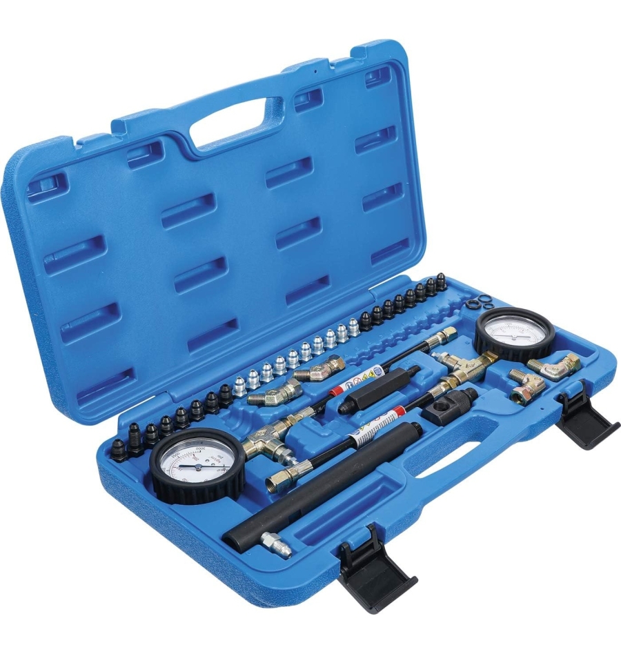
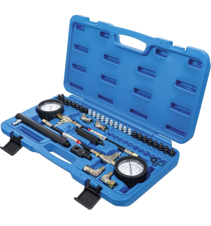
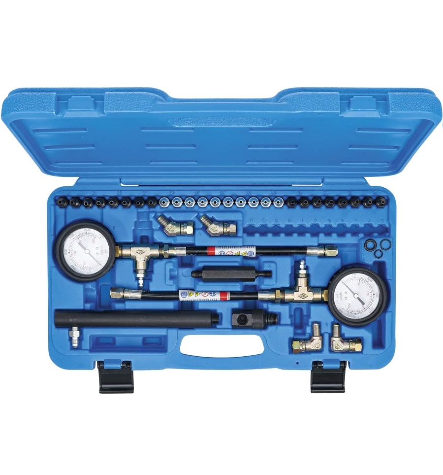
ABS and Brake Pressure Tester Kit
-
Code:6964
-
Weight:3.060 Kgs
Overview:
✔ Professional ABS and brake pressure tester for hydraulic brake systems
✔ Suitable for brake systems with and without ABS
✔ Designed for troubleshooting and pressure diagnostics of brake systems
✔ Enables testing of brake pressure regulators and proportioning valves
✔ Allows comparison of pressure differences between left/right and front/rear brakes
✔ Includes 2 pressure gauges with measurement range up to 3000 psi (200 kg/cm²)
✔ Supplied with a comprehensive adapter assortment for broad vehicle compatibility
✔ Suitable for professional workshop and automotive brake service use
This ABS and brake pressure tester kit is designed for measuring hydraulic brake pressure in braking systems equipped with or without ABS. The kit simplifies diagnostics and fault detection in hydraulic brake systems by allowing direct pressure measurement at various locations within the braking system.
The tool enables testing and inspection of brake pressure regulating valves, brake force regulators, residual pressure valves, and hydraulic system performance. It can also be used to determine pressure differences between the left and right sides as well as between front and rear brake circuits.
For proper diagnostics, measurements should be performed under normal operating conditions. On vehicles equipped with rear ride-height control valves, brake pressure at the rear axle should be checked with the vehicle resting on its wheels under normal load conditions.
Typical hydraulic brake pressure under firm brake pedal application generally falls within:
- 700–1500 psi
Rear brake pressure is typically lower than front brake pressure and may reach approximately:
- 60–80% of front brake pressure
Pressure differences between left and right sides should generally remain within:
- Maximum 10%
Suitable for professional workshops and brake system diagnostic operations.
Set Contents
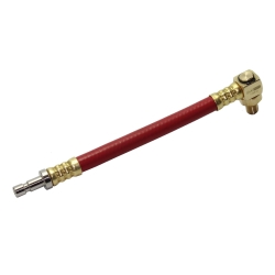
Pressure Gauges
- 2 pressure gauges
- Measuring range: 0–200 kg/cm²
- Measuring range: 0–3000 psi
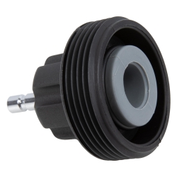
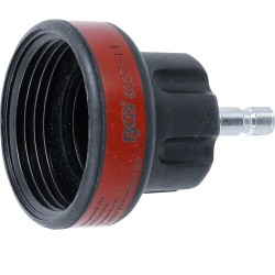
Adapters
- 2 × M10 × 1.5
- 2 × M10 × 1.0
- 2 × M7 × 1.0
- 2 × M8 × 1.25
- 2 × 3/8" × 24 UNF
- 2 × 1/4" × 28 UNF
- 2 × 7/16" × 24 UNF
- 2 × 7/16" × 20 UNF
- 2 × 5/16" × 24 UNF
- 2 × M8 × 1.0
- 2 × M10 × 1.0
- 2 × M10 × 1.25
- 2 × M6 × 1.0
Connection Components
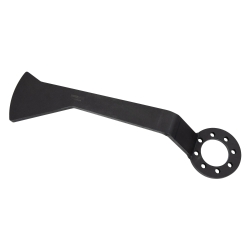
- 1 connection tube
- 1 connection elbow M14 × 1.5
- 1 connection tube M8 × 1.0
- 2 × 45° connection adapters
- 2 × 90° connection adapters
Applications
- Hydraulic brake system diagnostics
- ABS system pressure testing
- Brake pressure regulator testing
- Brake proportioning valve inspection
- Residual pressure valve testing
- Front and rear brake pressure comparison
- Left and right brake pressure comparison
Technical Features
- Suitable for brake systems with and without ABS
- Wide adapter selection for broad vehicle compatibility
- Dual pressure gauges for comparative testing
- Supports rapid brake system fault detection
- Professional workshop-grade construction
- Improves diagnostic accuracy
- Suitable for professional brake service applications
ABS and Brake Pressure Tester - Instructions
Structured English version with collapsible sections. All sections are closed by default, and only one section can be open at a time.
Application
This tool is intended for static brake pressure testing on hydraulic brake systems, including brake calipers, wheel cylinders, rear load-sensing valves, ABS hydraulic units and related brake pressure circuits.
General Instructions for Use
The correct adapters must be selected before use. Remove the bleed valves and connect the pressure gauges using the appropriate adapters.
The pressure gauges are connected to the front and rear brake calipers and/or wheel cylinders. To do this, remove the bleed valves, install the correct adapter, and then connect the pressure gauge.
Setup Procedure
- Select the correct adapters. Use the supplied vehicle application list to select the adapters suitable for the relevant vehicle make and model. When the correct adapters are selected, the threads and locking features will match the removed bleed valve exactly. If the vehicle is not listed, remove one front and one rear bleed valve and compare their threads with the supplied adapters. The bleed valve threads must be compared with the adapter thread end that screws into the brake caliper or wheel cylinder. One end of each adapter has a standard thread pitch for connection to the pressure gauge and hose fitting.
- Connect the pressure gauge hose. Attach the hose of the pressure gauge assembly to the adapter installed in the wheel cylinder or brake caliper. Tighten the connection securely.
- Install the adapter. Screw the adapter by hand into the bleed port of the brake caliper or wheel cylinder, then tighten it with a wrench.
- Bleed the pressure gauge and hose assembly. Hold the pressure gauge upright and open the bleed valve. Have a second person slowly and evenly depress the brake pedal. When brake fluid exits the bleed valve, close the bleed valve and instruct the second person to slowly release the brake pedal. The gauge line should now be bled. This ensures that all air is removed and that accurate hydraulic pressure readings are obtained.
- Optional vacuum bleeding. Air can also be removed from the pressure gauge and hoses using a vacuum bleeder. Open the bleed valve on the gauge hose again and connect the suction end of the vacuum bleeder to the bleed valve. Hold the pressure gauge as upright as possible, with the bleed valve slightly pointing upward while air is removed from the hose.
- Connect the second pressure gauge. Install and bleed the second pressure gauge in the same way.
Safety Information
- Do not drive the vehicle while the pressure gauges are installed.
- The tools are intended only for static testing on a test stand.
- Do not press the brake pedal with more than normal braking pressure.
- Exceeding the rated pressure of the gauge, measured in PSI, will damage the gauges and void the warranty.
Brake Testing — Residual Brake Pressure
If residual pressure remains in the disc brake system after the pedal is released, or if the pressure drops slowly, this can cause rapid wear and/or overheating of the pads, calipers and rotors.
Connecting pressure gauges is much more accurate than having a second person rotate the wheel manually, because a small amount of residual pressure or resistance can easily be overcome by the leverage of the wheel and tyre assembly.
On disc brake systems, the gauges should show pressure when the brake pedal is applied. When the pedal is released, the pressure gauge should no longer show any pressure.
Brake Testing — Air in the System or Internal Master Cylinder Seal Leakage
Do not suddenly press the brake pedal with force. For accurate measurement, the pressure increase and master cylinder actuation must occur gradually. Sudden brake pedal application, similar to emergency braking, will produce inaccurate pressure test results.
Air in the system or leakage at an internal master cylinder seal can be identified by using one pressure gauge on each side. When the pedal is applied, the pressure shown on one gauge may rise quickly, while the other side shows only a small increase.
The side with the low pressure increase may have air in the system, or an internal master cylinder seal may be leaking. To build pressure in the closed hydraulic system, apply the brake pedal slowly using light, controlled movements.
Brake Testing — Uneven Pad Wear or One-Sided Braking
If uneven pad wear exists between the sides, or if braking force is stronger on one side, connect the pressure gauges to both front brake calipers.
While a second person applies the brake pedal, check the brake pressure on both gauges. If the brake pressures at both wheels are equal, the problem may have a mechanical cause rather than a hydraulic one.
Testing Rear Load-Sensing Valves
The following general instructions are intended as guidelines for the correct use of pressure gauges when measuring brake pressure for the adjustment of rear ride-height/load-sensing valves.
A detailed workshop manual must be consulted for adjustment of the ride-height/load-sensing valve on the specific vehicle. The procedures described by the manufacturer must be followed. These general notes are only an overview of the required steps.
It is essential that the vehicle is positioned on a level surface and that the specified load, including the driver, is present in the vehicle. Pressure gauges must then be connected to the front and rear wheels.
Depending on the valve design, such as a rear brake pressure regulating valve or a dual-sensing/bypass valve, several pressure tests must be performed according to the manufacturer’s procedure.
Some vehicles are equipped with rear brake pressure regulating valves, including Ford Taurus and Sable sedans, Chrysler minivans, and passenger or off-road vehicles such as the Nissan Quest, Isuzu Pickup, Suzuki Sidekick, Toyota Pickup trucks and many others.
Where these valves are adjustable, manufacturer repair manuals specify detailed adjustment procedures. Where non-adjustable valves are installed, the manuals describe how to check the valves for serviceability and correct operation.
On valves that sense only rear pressure, rear brake pressure control depends on vehicle ride height. According to the service manual, the brake pedal usually has to be applied slowly, a specified front pressure must be built up, and the rear pressure must then be measured.
To check correct valve control, perform a simple test, then raise the rear of the vehicle, check the pressure, lower the rear of the vehicle again, and check the pressure once more. The ratio of rear brake pressure to front brake pressure should differ significantly between the two conditions.
Rear Load-Sensing Valve Testing — Dual-Sensing or Bypass Valves
- Apply force to the brake pedal slowly and in a controlled manner until the front brakes reach the pressure specified in the vehicle manufacturer’s manual. This pressure will likely be in the range of 780–1100 psi. In this condition, rear brake pressure should be approximately 55–75% of the front pressure.
- An incorrectly adjusted rear load-sensing valve can cause premature or very rapid wear of the front disc brake pads. High pedal force, rear wheel lockup on slippery road surfaces or in poor weather conditions, and strong rear brake pull to one side can indicate incorrect adjustment or malfunction of the rear load-sensing valve. Without a pressure gauge such as an ABS and brake pressure tester, the hydraulic cause of these problems is almost impossible to identify.
- Continue increasing brake pedal pressure slowly and in a controlled way, making sure that pressure rises at both the front and rear. When front hydraulic pressure reaches approximately 1300–1700 psi, rear brake pressure should have increased to approximately 80–85% of the front pressure. These pressure values are based on data collected from manufacturer manuals for several different vehicles. Always use the manufacturer or service manual to determine the exact pressures required for the vehicle being tested.
- When used with the correct supplied adapters, the ABS and brake pressure tester makes it possible to check the function of various rear brake pressure regulating valves. This can help diagnose the causes of rapid front pad wear, rear wheel lockup problems and other brake faults that cannot be identified without effective pressure gauges.
Testing Anti-Lock Braking Systems
Anti-lock braking systems, or ABS, are available in standalone and non-standalone designs.
Standalone ABS: A self-contained unit that houses the electrical and mechanical components required for brake control and power assistance. A standalone system does not use the conventional master cylinder and brake booster. Instead, it performs these functions as a separate hydraulic unit.
Before testing or servicing a standalone ABS, the unit must be depressurised for safety reasons because it is a high-pressure system.
Non-standalone ABS: A low-pressure system that uses the existing master cylinder and brake booster. To provide anti-lock braking functions, it uses special electronic components integrated into the existing conventional brake system.
Testing Standalone Anti-Lock Braking Systems
When pressure testing the master cylinders of standalone ABS systems, pump pressure and accumulator pressure must be determined. In all standalone ABS master cylinders, brake power assistance is generated by the pump and accumulator. ABS and manufacturer manuals contain specific manufacturer instructions for these pressure tests.
The pressure at the master cylinder outlet and the pedal force required to achieve the desired pressure vary significantly if the accumulator and pump are not functioning correctly.
On some standalone ABS systems, rear brake pressure can only be checked at the wheel because it is generated solely by the accumulator. For this reason, standalone ABS master cylinders should only be tested according to manufacturer procedures. These procedures do not include checking outlet pressure directly at the master cylinder ports.
If manufacturer diagnostic procedures are not followed when checking outlet pressure, the diagnosis may be misleading. Because the fluid in the accumulator is under high pressure, special attention must be paid to safety.
If master cylinder outlet pressure needs to be determined, first perform the manufacturer’s procedure for checking correct accumulator and pump pressure, then measure outlet pressure at the wheels.
Service Safety Notice for Standalone ABS
Before all pressure tests on the master cylinder, the accumulator must be discharged.
- Turn the ignition key to the OFF position.
- Press the brake pedal 25 to 35 times until it feels rock hard.
- Press the pedal a further 5 times.
- Only after accumulator pressure has been released may the adapter and pressure gauge be safely installed or removed.
Pressure Tests on Standalone DELCO III ABS Master Cylinders
The following tests can be used to check loss of nitrogen charge in the upper part of the accumulator bladder, determine total system pressure, approximately assess pump performance, and verify operation of the high- and low-pressure switches on DELCO III systems.
Applications: Various Buick Regal, Oldsmobile Cutlass Supreme, Jeep Cherokee and Pontiac Grand Prix models, model years 1989–1997.
- Inspect the lower threaded area of the accumulator to ensure that the O-ring has not remained stuck to the master cylinder. Also inspect the O-ring for nicks, cuts or cracks. Replace damaged O-rings.
- Loosen the accumulator from the integrated master cylinder at the Allen or Torx screws using a 3/8" ratchet wrench. The screws are located in the Torx or Allen recess on top of the accumulator.
- Depressurise the accumulator. With the ignition key in the OFF position, press the brake pedal 20 to 30 times until it feels rock hard. Press the pedal a further 5 times.
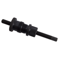
- Take ABS Adapter P from the pressure gauge set and check whether it has an O-ring at the threaded end. Screw the adapter hand-tight into the master cylinder.
- Screw the accumulator, with an undamaged O-ring, onto the top of Adapter P. Tighten the accumulator lightly by hand. After the accumulator is correctly tightened, the adapter may screw itself slightly further into the master cylinder.
- Connect the pressure gauge to the adapter and tighten the connection with a wrench. Pressure and pump run tests can now be performed on the standalone DELCO III ABS unit.
- Take ABS Adapter P from the pressure gauge set and check whether it has an O-ring at the threaded end. If an O-ring is present, screw Adapter P by hand into the Adapter P that is already installed in the master cylinder.
Pressure Tests on TEVES II ABS Master Cylinders
The following tests can be used to determine loss of nitrogen charge in the upper part of the accumulator bladder, determine total system pressure, approximately assess pump performance, and verify operation of the high- and low-pressure switches.
Applications: Various GM, Ford, Saab, Merkur, Peugeot and Volkswagen models, model years 1985–1990.
- Depressurise the accumulator. With the ignition key in the OFF position, press the brake pedal 20 to 30 times until it feels rock hard. Press the pedal a further 5 times.
- Inspect the lower threaded area of the accumulator to ensure that the O-ring has not remained stuck to the master cylinder. Also inspect the O-ring for nicks, cuts or cracks. Replace damaged O-rings.
- Loosen the accumulator from the integrated master cylinder at the Allen or Torx screws using a 3/8" ratchet wrench. The screws are located in the Torx or Allen recess on top of the accumulator.
- Screw the accumulator, with an undamaged O-ring, onto the top of the adapter. Tighten the accumulator lightly by hand. After the accumulator is correctly tightened, the adapter may screw itself slightly further into the master cylinder.
- Take the ABS adapter from the pressure gauge set and check whether it has an O-ring at the threaded end. Screw the adapter hand-tight into the master cylinder.
- Connect the pressure gauge to the adapter and tighten the connection with a wrench. Pressure and pump run tests can now be performed on the standalone TEVES II ABS unit.
Standalone ABS Pressure Test Procedure
- Have a second person sit in the vehicle and, when instructed, turn the ignition key to the ON position without starting the engine. Hold the pressure gauge so the display is clearly visible. Read and record the initial value as the ignition is switched ON and the pump begins to run. The initial pressure reading indicates the remaining nitrogen charge in the upper part of the accumulator bladder. A reading of approximately 1100 psi is normal when the system is operating correctly.
- Record the pump run time between switching the ignition ON and the pump stopping. Normal pump run time to fully charge the accumulator is 45–60 seconds. Also observe the system pressure shown on the gauge when the pump stops. On most units, the pressure should be around 2500 psi.
- With the ignition key still in the ON position, apply the brake pedal with normal pressure, as if stopping the vehicle from 50 km/h. Repeat this 2 to 3 times and record the pressure drop at each application. Normal pressure drop per application is approximately 100–150 psi. After 2 to 3 applications, the pump starts to restore system pressure. The pressure at which the pump restarts should be approximately 1100–1200 psi. Normal pump run time to recharge the system after 2 to 3 pedal applications is 6 to 8 seconds. The gauge pressure when the pump switches off should match the pressure from the first test.
- With the ignition key still in the ON position, check whether system pressure remains stable. There should be little or no pressure drop over a period of two minutes. If the pressure drops significantly, or drops enough for the pump to start within two minutes, there is an internal cross-leak in the unit.
- According to manufacturer instructions, the O-ring must be replaced every time the accumulator is removed and reinstalled in the vehicle. Install a new O-ring, reinstall the accumulator in the master cylinder and tighten it to the correct torque.
- Turn the ignition key to the OFF position. Press the pedal 20 to 30 times until it feels rock hard. Press the pedal a further 5 times. Hold the adapter and unscrew the accumulator from the adapter. Check the bottom of the accumulator to verify that the O-ring is still present. Check the condition of the O-ring. Unscrew the pressure gauge from the adapter and then remove the adapter from the master cylinder. Check the O-ring at the bottom of the adapter.
- Check the fluid level according to the instructions on the side of the master cylinder reservoir. GM checks its TEVES II master cylinders with the accumulator discharged, ignition OFF and accumulator discharged. Ford checks its TEVES II units with the accumulator charged, ignition ON and accumulator under pressure.
Pressure Port Tests on Bendix 10
In the case of various malfunctions in a Bendix 10 ABS unit, fault codes may be displayed on the vehicle dashboard or red/yellow warning lamps may illuminate. If this occurs, follow the diagnostic procedure described in the vehicle owner’s or service manual for the indicated code or fault.
If the ABS technician manual specifies a pressure test at an output port of the Bendix 10 unit, the ABS and brake pressure tester can be used by following the steps below.
Applications: Various Chrysler vehicles, model years 1990–1993.
- After depressurising the accumulator, use an 11 mm box wrench to remove the plug on the side of the Bendix 10 ABS unit. After removing the plug, inspect the O-ring on the plug for damage. If damaged, replace the O-ring before reinstalling the plug.
- Install Adapter 09 into the opening from which the plug was removed. Tighten the adapter using an 11 mm box wrench.
- Check the bleed valve directly below the gauge head. Ensure that it is closed. Tighten this valve with a box wrench so that it seals securely.
- Connect the pressure gauge to the adapter that was installed on the side of the Bendix 10 unit.
- Perform pressure checks and tests according to the ABS technician manual.
- Remove the pressure gauge from the adapter, then remove the adapter from the test port.
- After completing the required pressure tests, depressurise the system again. First turn the ignition key to the OFF position and remove it from the ignition lock. Press the brake pedal 40 times to reduce system pressure.
- Check the brake fluid level and top up if necessary to reach the correct system level.
- Reinstall and tighten the test port plug. Before installing the plug, make sure the O-ring is in good condition.
Pressure Tests on Bendix 9 ABS
Applications: Jeep Cherokee and Wagoneer, model years 1989–1991.
Follow the relevant manufacturer diagnostic and pressure testing procedures for Bendix 9 ABS systems. Use the correct adapter and pressure gauge connection according to the service information for the specific vehicle.
Pressure Tests on Standalone Bosch 3 ABS
Always follow the diagnostic procedure described in the vehicle service manual for the indicated fault. If the ABS technician manual specifies a pressure test on the standalone Bosch ABS, the test is performed through the bleed valve on the side of the unit.
By using Adapter 05, the ABS and brake pressure gauge set can be used for this test.
Applications: Various Chrysler and Cadillac vehicles, model years 1987–1992.
- After depressurising the accumulator, remove the bleed valve on the side of the Bosch ABS unit.
- Connect the pressure gauge to Adapter 05, which is to be installed on the side of the unit.
- Install Adapter 05 into the opening from which the bleed valve was removed.
- Perform pressure tests according to the ABS technician manual. After completing the required pressure tests, depressurise the system again. Turn the ignition key to the OFF position and remove it from the ignition lock. Press the brake pedal 40 times to reduce system pressure.
- Reinstall and tighten the bleed valve. Check the brake fluid level and top up with the required amount if necessary.
- Remove the pressure gauge from the adapter, then remove the adapter from the bleed valve opening.
Additional ABS System Notes
In addition to the systems listed above, many other standalone and non-standalone anti-lock braking systems require specific pressure tests during diagnosis.
If the relevant ABS manual specifies a pressure test and mentions a particular manufacturer tool, check where the pressure is to be measured. On many units, bleed valves or bleed plugs are screwed into the side of the master cylinder.
Follow the correct depressurisation procedure for the unit. Remove the bleed valve or bleed plug and compare it with the various adapters in the set. In many cases, one of the bleed valve adapters can be installed, allowing the ABS and brake pressure tester to be connected directly to the bore from which the bleed valve was removed.
Great care has been taken to provide technicians with as complete a set of adapters and instructions as possible for most pressure measurement applications.
Manufacturer procedures regarding ignition key position, pedal operation and indicated pressure values must always be observed.
Because many different systems exist and these systems are continuously updated and changed, no documentation can reliably specify the correct adapter for every system. However, the adapters supplied with the product cover most applications encountered in practice.