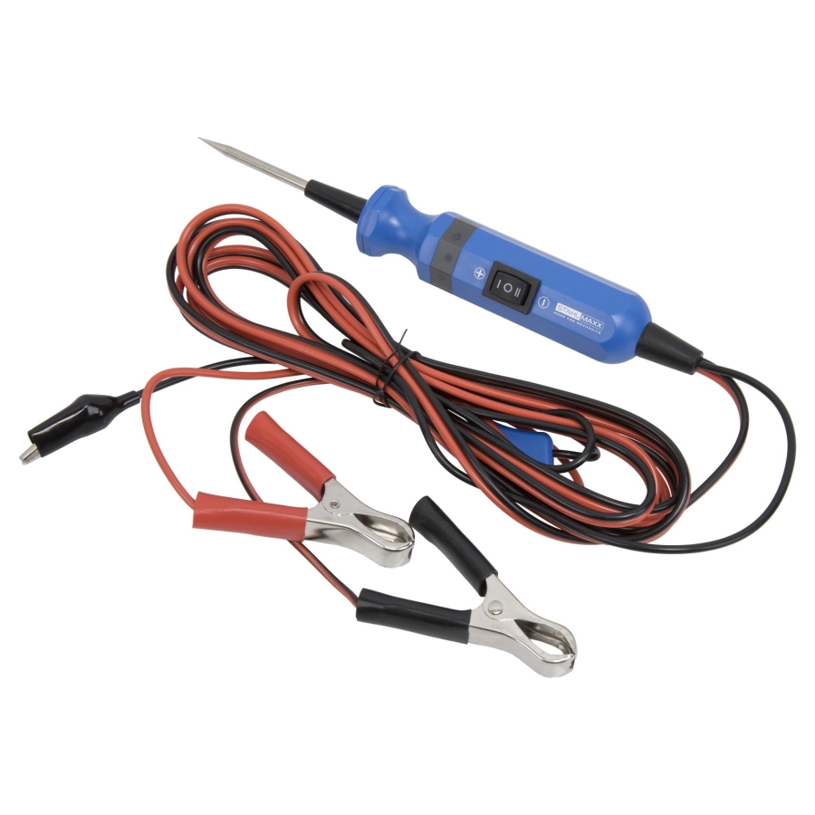
Automotive Continuity and Voltage Tester 6V / 12V / 24V
-
Code:120471
-
Weight:0.334 Kgs
Overview:
✔ Professional voltage and continuity tester for automotive electrical systems
✔ Suitable for 6V, 12V and 24V systems
✔ Performs polarity, circuit, ground and component testing
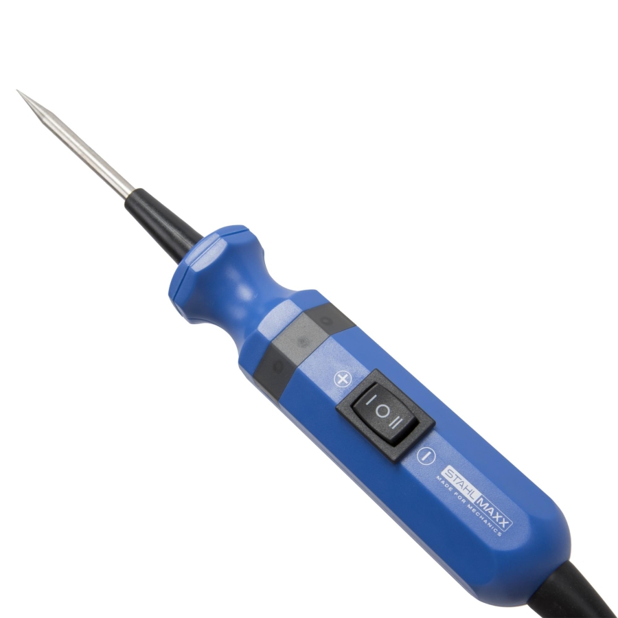
✔ LED indication with positive and negative polarity detection
✔ Audible signal for ground connection verification
✔ Automatic overload protection above 10A
✔ 4 m connection cable for flexible operation

The Automotive Continuity and Voltage Tester 6V / 12V / 24V is designed for fast and efficient diagnostics of electrical systems and components in cars, commercial vehicles, motorcycles, construction equipment and similar applications.
The tester allows technicians to quickly identify faults within electrical circuits and perform various diagnostic procedures including polarity testing, circuit testing, ground connection verification and component testing.
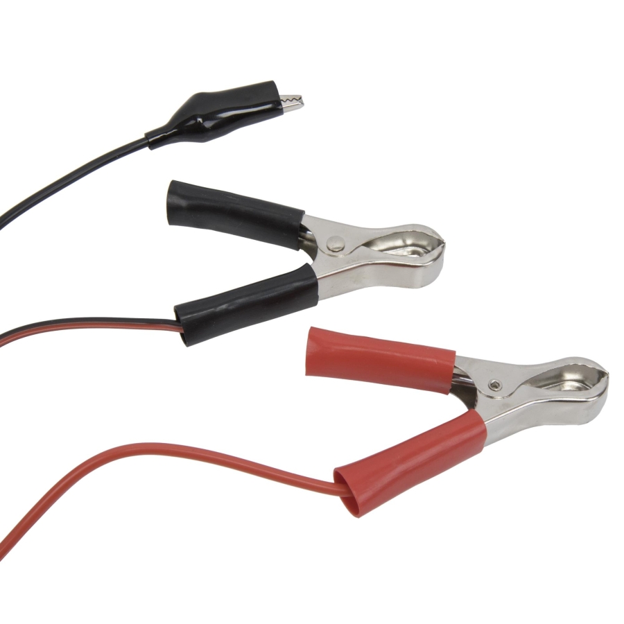
The unit connects directly to the vehicle battery using the supplied battery clamps, which provide power to the tester and establish a reference potential for polarity detection. The integrated 4-meter cable allows convenient access during testing.
For additional protection, the tester includes an automatic overload protection function. If current exceeds 10A, the tester automatically interrupts the circuit and activates an audible warning signal to prevent damage to the tester and connected components.
Testing Functions
Polarity Test
Touch a terminal or contact with the probe tip to identify polarity:
- Red LED: Positive (+) pole
- Green LED: Negative (-) pole
Circuit / Cable Test
Checks for interruptions or open circuits in wiring and electrical systems:
- Green LED ON: Circuit closed
- Green LED OFF: Circuit interrupted
Ground Connection Test
Detects poor grounding conditions caused by weak connections or excessive resistance:
- Red LED: Poor ground connection detected
- Green LED: Sufficient ground connection
- Audible signal: Near-zero voltage drop ground connection
Component Test
Allows testing of installed or removed electrical components:
- Ground clamp connects to component negative terminal
- Probe connects to positive terminal
- Pressing the "+" switch supplies the required voltage to the component
Suitable for testing:
- Relays
- Motors
- Solenoids
- Electrical actuators
- Other electrical components
Technical Specifications
- Operating voltage: 6V / 12V / 24V
- Overload protection: Automatic above 10A
- Connection cable length: 4 m
- Polarity indication: Red/Green LED
- Audible indication: Yes
- Power source: Vehicle battery connection
Package Contents
- 1 × Voltage and continuity tester with battery and ground clamps
Important Safety Information
This product is an electrical device intended for operation by trained personnel only. Always follow manufacturer instructions and applicable safety guidelines when working with electrical systems.
Using the Voltage and Continuity Tester
WARNING: A test current applied toward the control unit (ECU) may damage it. Components and wiring leading to the control unit must only be tested with the connector disconnected.
Polarity Test
Used to determine polarity within an electrical circuit.
- Unroll the cable.
- Connect the red clamp to the positive terminal of the vehicle battery.
- Connect the black clamp to the negative terminal of the vehicle battery.
- Touch the test probe to the component to be tested:
→ LED illuminates Red = Positive polarity
→ LED illuminates Green = Negative polarity
Circuit Test
Used to check for an open (broken) or closed circuit.
- Unroll the cable.
- Connect the red clamp to the positive terminal of the vehicle battery.
- Connect the black clamp to the negative terminal of the vehicle battery.
- Connect the ground clamp to one end of the cable being tested and touch the other end of the cable with the test probe.
→ LED illuminates Green = Circuit is closed
→ LED remains off = Circuit is open
Testing Components Outside the Circuit
(e.g. relays, fuel pumps, window motors, switches, lamps, etc.)
Used to determine whether a component is faulty.
- Unroll the cable.
- Connect the red clamp to the positive terminal of the vehicle battery.
- Connect the black clamp to the negative terminal of the vehicle battery.
- Connect the ground clamp to the negative terminal of the component being tested.
- Touch the positive terminal of the component with the test probe and operate the switch.
→ The component should now activate and perform its function
→ If the tester switches off, an overload condition exists and the component should be inspected
Testing Components Within the Circuit
Used to determine whether a component is faulty.
- Unroll the cable.
- Connect the red clamp to the positive terminal of the vehicle battery.
- Connect the black clamp to the negative terminal of the vehicle battery.
- Components with an existing ground connection can also be tested without using the tester ground clamp.
- Press the switch to supply power to the positive terminal of the component through the tester.
Bypass Function
Used to bypass suspected disconnected or broken wires. Since the black battery clamp and the crocodile ground clamp are internally connected, a positive connection can also be established.
- Unroll the cable.
- Connect the black clamp to the positive terminal of the vehicle battery.
- Connect the crocodile ground clamp after the suspected wire interruption point.
Ground Connection Test
- Unroll the cable.
- Connect the red clamp to the positive terminal of the vehicle battery.
- Connect the black clamp to the negative terminal of the vehicle battery.
- Press the switch – if no ground connection exists, the LED will illuminate Red.
- Move the test probe along the wire.
- Once negative voltage is detected, the LED will illuminate Green.
- If an audible signal is heard simultaneously, the ground connection has little or no voltage drop.
Short Circuit Detection and Localization
- Unroll the cable.
- Connect the red clamp to the positive terminal of the vehicle battery.
- Connect the black clamp to the negative terminal of the vehicle battery.
- Remove the component fuse (if blown) from the fuse box and begin testing at the contact leading to the component. (The presence of voltage can also be checked immediately.)
- Press and hold the button and briefly touch the contact with the test probe. If the LED illuminates Green and the buzzer sounds, a short circuit or overload on this wire is likely.
Follow the cable or connection, if necessary using a wiring diagram. Disconnect the wire at an appropriate point and repeat the test in that direction.
If a short circuit is still present, repeat the procedure until the fault is located. If the test is unsuccessful, remove the connected component and test it separately.