Engine Timing Tool Kit for Jaguar, Land Rover, Ford, PSA 2.0–3.2 Diesel
-
Code:9010
-
Weight:1.281 Kgs
Overview:
✔ Engine timing tool kit for 2.0, 2.2, 2.4 and 3.2 diesel engines
✔ Suitable for Ford, Citroën, Peugeot, Jaguar, Land Rover and Fiat
✔ Designed for timing adjustment and engine repair work
✔ Required for valve train service and cylinder head gasket replacement
✔ Compatible with Duratorq (Puma) diesel engines
✔ Includes locking, holding and alignment tools
✔ Ideal for professional workshop use
This engine timing tool kit is designed for checking and adjusting engine timing on a wide range of diesel engines used across Ford, PSA, Jaguar and Land Rover vehicles.
It is required for precise timing alignment during operations such as valve train service and cylinder head gasket replacement.
Compatibility
Suitable for:
- Ford Mondeo (2000–2007), Transit (2000–2011)
- Citroën Relay (2006–2011), Jumper III
- Fiat Ducato (2006–2011)
- Jaguar X-Type (2001–2010)
- Land Rover Defender (2007–2011)
- Peugeot Boxer III (2006–2011)
- LDV Convoy (2002–2006)
Engine Types
Duratorq (Puma) diesel engines:
2.0L:
ABFA, D3FA, D5BA, D6BA, F3FA, FIFA, FMBA, HJBA, HJBB, HJBC, HJBE, N7BA, N7BB
2.2L (chain-driven high-pressure pump):
QJBA, QJBB, QJBC, QJBD
2.2L (camshaft-driven high-pressure pump):
4HM, 4HU, 4HV, P8FA, P22DTE, QVFA, QWFA
2.4L:
244DT, DOFA, D2FA, D2FB, D4FA, F4FA, FXFA, H9FA, H9FB, HEFA, HFFA, JXFA, PHFA, ZSD424
3.2L:
SAFA (timing only)
Functionality
The kit enables:
- Accurate locking and alignment of engine timing components
- Secure flywheel and crankshaft positioning
- Proper handling of high-pressure pump gears
- Reliable execution of timing-related service procedures
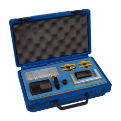
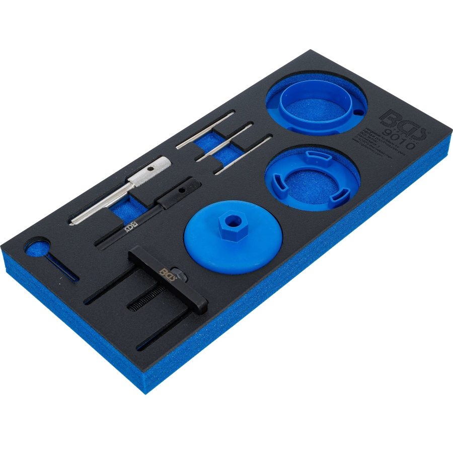
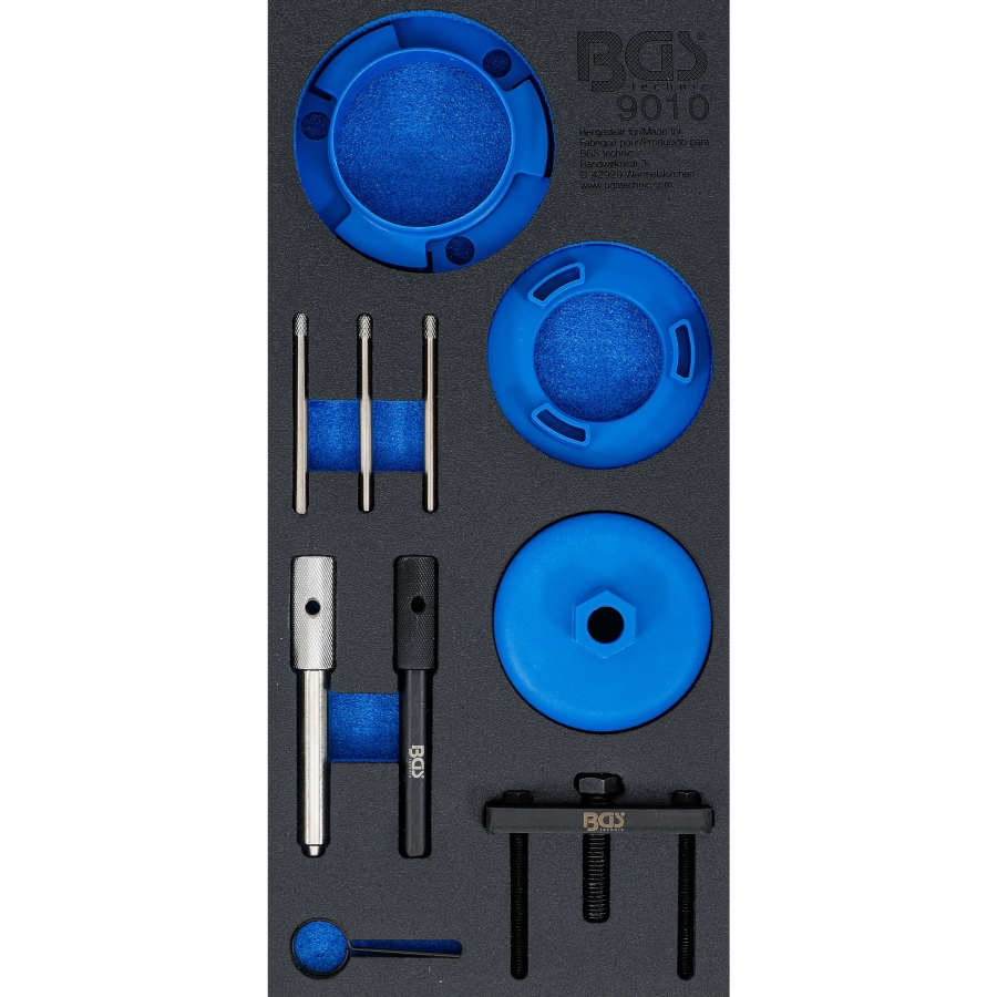
Contents
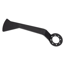
- Engine cover alignment tool (as OEM 303-682)
- Engine cover / crankshaft radial seal tool (as OEM 303-679A)
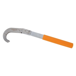
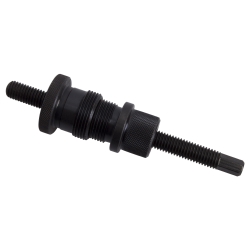
- High-pressure pump gear holding tool (as OEM 303-1151)
- High-pressure pump gear removal tool (as OEM 303-249)
- Flywheel locking bolt (as OEM 303-675)
- Flywheel locking bolt (as OEM 303-698)
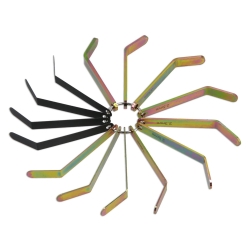
- Locking pin set, 3 pcs, 6 mm
- Tensioner locking pin, 2 mm
OEM Reference
Designed for use as:
Ford:
303-682, 303-679A, 303-1151, 303-249, 303-675, 303-698
Fiat:
2000016500, 2000001000, 2000017100
Citroën / Peugeot:
0198B2, 0198A, 0198J
Jaguar & Land Rover:
303-698
Original numbers are used for comparison purposes only, this is not an original tool!
Flywheel Locking
Remove the crankshaft sensor and rotate the engine clockwise until the flywheel locking position is reached. Insert the locking pin and carefully rotate the crankshaft until it engages in the flywheel slot. The crankshaft will be positioned approximately 50° before Top Dead Center (BTDC).
Important: Do not use the locking pin to counterhold the crankshaft when loosening or tightening bolts. Do not rotate the engine while the locking pin is installed.
Camshaft & Injection Pump Alignment
Install the locking pins to secure the camshafts and injection pump in their timing positions. Ensure all timing holes and reference marks are correctly aligned before loosening or tightening sprocket bolts. Components should only be adjusted while properly locked.
Timing Chain & Tensioner
Retract and lock the timing chain tensioner before removal. Remove the chain, guides, and sprockets, marking their positions if required.
During installation, align all timing marks (including colored chain links where applicable) with the corresponding sprockets. Ensure the chain is correctly tensioned on the non-loaded side before tightening.
Tighten camshaft and pump sprocket bolts initially hand-tight, then torque to manufacturer specifications.
Timing Verification
Rotate the engine manually two full revolutions in the normal direction of rotation. Return to approximately 50° BTDC and reinsert the locking tools.
Verify that all locking pins can be reinstalled without force. If alignment is incorrect, repeat the timing procedure.
Important: Never loosen sprocket bolts unless the system is correctly locked.
Front Cover Installation
Ensure all sealing surfaces are clean and free of old sealant. Apply a uniform bead of suitable sealant (approx. 2–3 mm) to the mating surface.
Install the front cover aligned with the crankshaft to prevent premature seal wear. Tighten all fasteners evenly to the specified torque.
Fuel Injection Pump (General Notes)
- Clean all fuel system components thoroughly before disassembly
- Seal all openings immediately to prevent contamination
- High-pressure fuel lines must be replaced after removal
- Ensure the pump gear is securely locked before loosening mounting bolts
Depending on engine type, the injection pump can be removed without affecting engine timing if the gear is properly secured.
During installation:
- Tighten mounting bolts to manufacturer specifications
- Typical reference values (may vary by engine):
- Pump mounting bolts: approx. 20–30 Nm
- Sprocket bolts: approx. 30–60 Nm
- High-pressure fuel lines: approx. 30–35 Nm
After installation, verify correct timing and system operation.
Note
This is a general overview of tool usage. Always follow the manufacturer’s specifications for exact procedures, torque values, and engine-specific requirements.