Complete Injector Removal and Installation Tool Set for BMW/MINI B38, B46, B48, B58 Direct-Injection Engines
-
Code:999172
-
Weight:5.080 Kgs
Overview:
✔ Complete set for removing and installing direct-injection injectors
✔ Suitable for BMW and MINI B38, B46, B48 and B58 engines
✔ Removal bridge allows injectors to be removed for reuse
✔ Threaded adapter and slide hammer for quickly removing injectors being replaced
✔ Includes installation tools for Teflon injector sealing rings
✔ Improved design permits direct access with a 24 mm socket

The direct-injection injectors used in BMW and MINI B38, B46, B48 and B58 engines feature a long plastic construction. High temperature fluctuations and seized injectors can cause cracking during removal, potentially resulting in fuel leakage and a vehicle fire.
This complete professional tool set provides different removal methods depending on whether the injectors will be reused or replaced.
Removal of Injectors for Reuse
If the injector is to be reinstalled, it must be removed using the supplied removal bridge. This method applies the extraction force in a controlled manner and reduces the risk of damaging the injector.
Removal of Injectors for Replacement
If the injector will be replaced, it can be removed quickly using the supplied threaded adapter and slide hammer. This eliminates the need to install the complete removal bridge.
Teflon Sealing Ring Installation
The set includes three installation sleeves and one installation cone for fitting the Teflon sealing rings to the injectors.
Improved Tool Design
The diameter of the upper knurled screws has been reduced compared with the original tool design. This allows a 24 mm socket to engage directly with the hexagonal profile.
A torque wrench can therefore be applied directly to tighten the tool accurately.
Maximum tightening torque: 7 Nm
Compatible Engine Codes
B38, B46, B48, B58
To Be Used as BMW and MINI
130190, consisting of 130192, 130193, 130194 and 130195
2358417, 2358022, 83302358417, 83302358022
Scope of Delivery
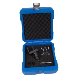
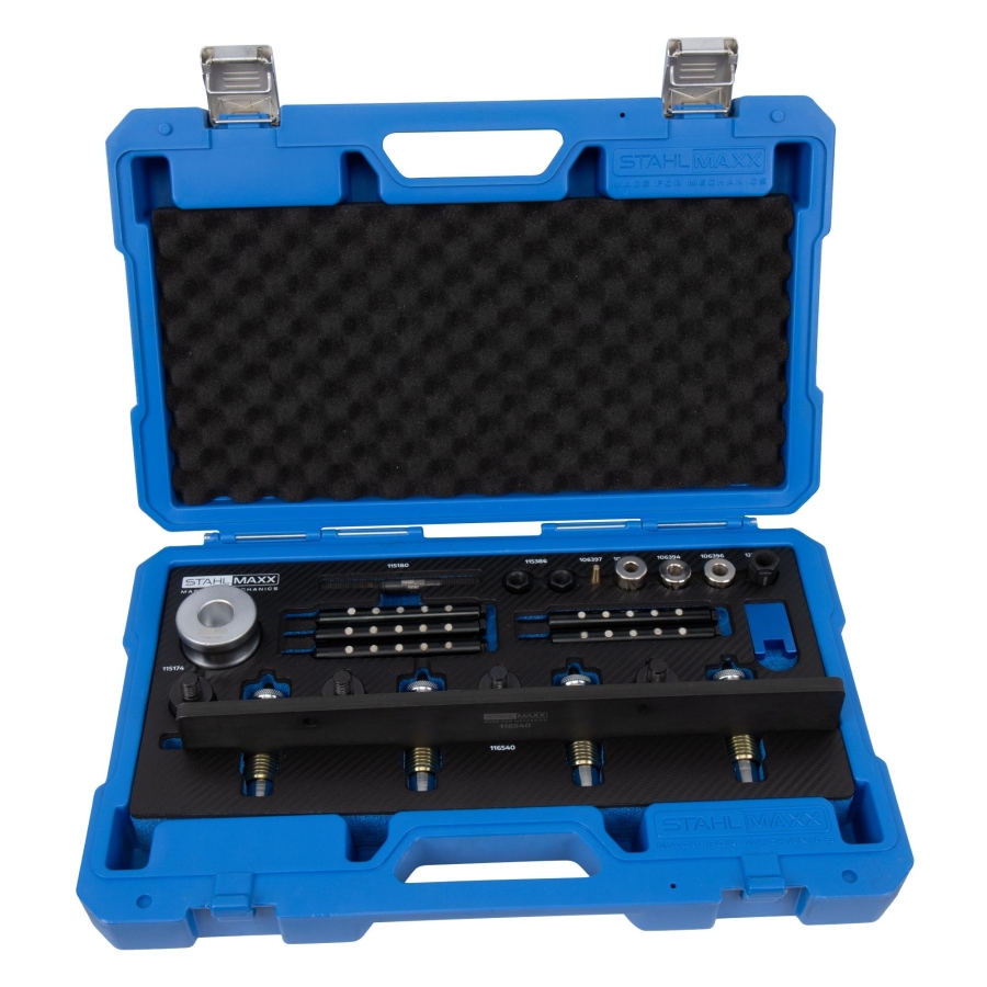
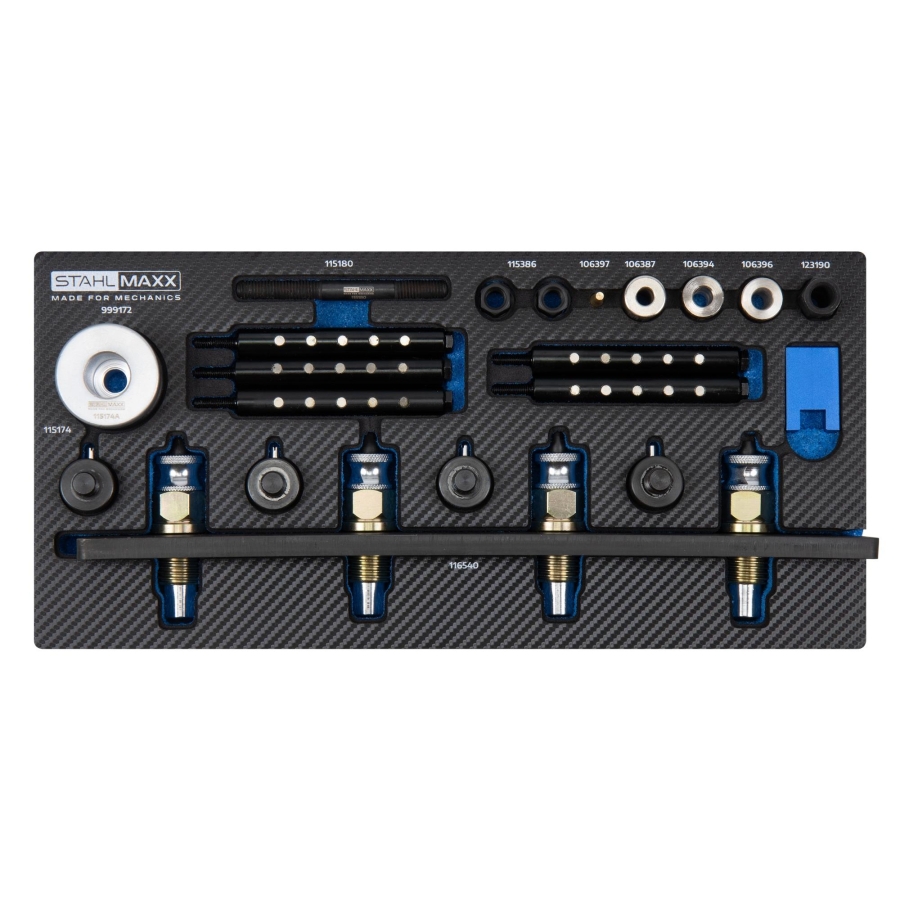
1 × injector removal and installation tool for BMW B38, B46, B48 and B58, item no. 116540A, to be used as BMW 2358417 and 2358022
1 × small installation sleeve for BMW injector sealing rings, item no. 106387, to be used as BMW 130194
1 × medium installation sleeve for BMW injector sealing rings, item no. 106394, to be used as BMW 130193
1 × large installation sleeve for BMW injector sealing rings, item no. 106396, to be used as BMW 130192
1 × installation cone for BMW injector sealing rings, item no. 106397, to be used as BMW 130195
1 × threaded adapter, female thread M12 × 1.5 to female thread M10 × 1.5, item no. 123190
1 × slide-hammer rod, 100 mm, M10 × 1.5, item no. 115180
1 × slide-hammer weight, 555 g, 50 × 48 mm, item no. 115174
1 × set of 2 hexagonal slide-hammer stop nuts, AF14, item no. 115386
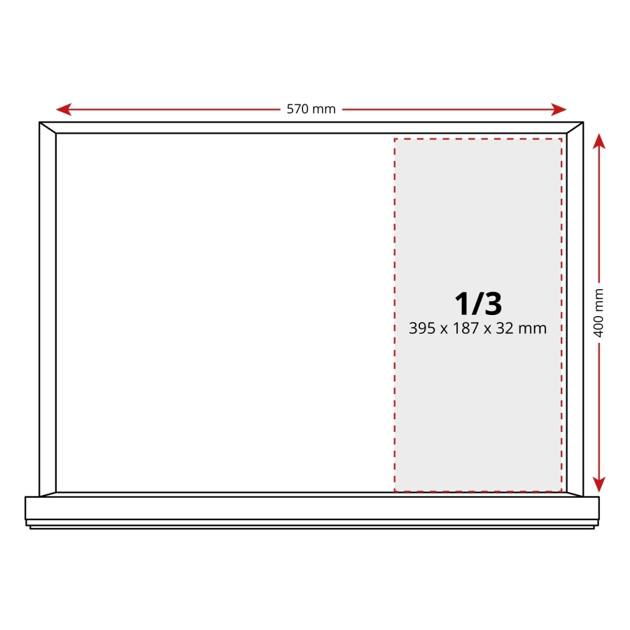
1 × fitted 1/3 foam insert, 395 × 187 × 32 mm, item no. 116540S
1 × 1/3 storage case, item no. 115269
Original numbers are provided for comparison purposes only. This is not an original tool.
Safety Precautions
Before starting work, observe the following precautions:
-
Follow all applicable safety procedures and maintain a clean working environment.
-
Do not allow ignition coils to come into contact with fuel.
-
Do not contaminate injector seals with oil.
-
Warning: Maximum pulling force: 2,000 N. Maximum torsional load: 6 Nm.
-
Always follow the manufacturer's specified tightening torques and tightening sequences.
-
Excessive force may damage the injector weld seams, which can result in fuel leaks.
Removal – Preparation
Before removing the injectors, complete the following steps:
-
Remove the air filter housing, engine cover, and ignition coils.
-
Disconnect the injector wiring harness. Pay attention to the dual-locking connector system.
-
Remove the oil filler cap and oil splash guard.
-
Disconnect the high-pressure fuel pump electrical connector, observing its dual-locking mechanism.
-
Remove the high-pressure fuel line between the rail and the pump, and disconnect the high-pressure sensor connector.
Fuel Rail Removal
The number of fuel rail mounting bolts depends on the engine configuration (3, 4, 6, or 8 cylinders).
-
Loosen the injector retaining bolts (M5 × 30 mm) in pairs.
-
6 or 8 bolts depending on engine version.
-
Always replace these bolts during reassembly.
-
-
Remove the fuel rail mounting bolts (M6 × 30 mm) securing the rail to the cylinder head.
-
4 bolts.
-
Always replace these bolts.
-
Important: Do not remove the fuel rail together with the injectors.
-
Carefully lift the fuel rail upward while leaving the injectors installed in the cylinder head.
-
Some engines may be equipped with helium indication seals beneath the fuel rail. These seals can be removed and are not reused during installation.
Installing the Pulling Device
Install the Injector Adapter
-
Remove the injector adapter from the pulling tool.
-
Install the adapter onto the injector while ensuring locking lever B remains in the upper position.
-
Rotate the adapter 90° and press lever B downward to lock it securely onto the injector.
Install the Pulling Bridge
-
Press the release mechanism of locking sleeves A and remove the threaded inner sleeves C.
-
Position the pulling bridge over the injectors.
-
Install the four bridge mounting bolts and tighten them finger-tight.
-
Fully screw in the extractor threads D (left-hand thread).
-
Reinstall the threaded inner sleeves C and hand-tighten them into the injector adapters.
-
Tighten the pulling bridge mounting bolts to 5 Nm.
Injector Removal
-
Set a torque wrench to 7 Nm.
-
Using a long 24 mm socket, rotate clockwise (standard right-hand thread) until the injector is extracted.
Warning: If more than 7 Nm is required to remove an injector, the injector must be replaced.
-
Remove each injector individually until the extractor threads reach their end position.
-
Release each injector from the pulling bridge by lifting locking lever B and rotating the adapter 90° counter-clockwise.
Before reinstalling the injectors:
-
Replace all injector sealing rings and decoupling washers.
-
Replace all injector retaining bolts and all fuel rail mounting bolts.
-
If injectors are replaced or installed in different cylinders, perform an injector quantity calibration (injector coding) according to the manufacturer's procedure.
Injector Installation
-
If necessary, press the injector retaining bracket over the bayonet fitting.
Important: If the retaining bracket has a cast locating tab, it must face toward the fuel rail.
-
Install new injector retaining bolts (M5 × 30 mm, two per injector).
-
Position spacer gauge F between the injector and the fuel rail.
-
Tighten the bolts finger-tight.
-
Remove the spacer gauge and repeat the procedure for every injector.
-
Before installing the fuel rail, ensure all injector electrical connectors are aligned parallel and move freely.
Fuel Rail Installation
Ensure the injector locating tabs are correctly engaged in the locating holes of the cylinder head.
-
Press the fuel rail downward until slight resistance is felt.
-
Install the two M6 × 30 mm bolts on the oil filler cap side.
-
Tighten these bolts alternately in 180° increments until the fuel rail seats fully.
-
Install the remaining two M6 × 30 mm bolts.
-
Tighten all four fuel rail bolts in a cross pattern to 5 Nm.
Injector Bolt Tightening Procedure
-
Install all injector retaining bolts (6 or 8 depending on engine version).
-
Tighten the bolts alternately in 180° increments until finger-tight.
-
Set the torque wrench to 5 Nm.
Starting from Cylinder 1 (front of the engine):
-
Tighten injector bolt 1 by 90° ±15°
-
Tighten injector bolt 2 by 90° ±15°
-
Repeat these two steps until 5 Nm is reached.
Continue with:
-
Injector bolts 3 and 4
-
Then bolts 5 and 6
-
Finally bolts 7 and 8 (where applicable)
Always tighten injector bolts in pairs using the same sequence.
Final Angle Tightening
-
Mark each injector retaining bolt with a straight reference line using a paint marker.
-
Tighten the bolts in sequence:
1 → 2 → 3 → 4 → 5 → 6 → 7 → 8
Each bolt should be tightened by 90° ±15°.
Verify that all reference marks have rotated approximately 90°.
Final Fuel Rail Tightening
-
Loosen the four M6 × 30 mm fuel rail mounting bolts.
-
Beginning on the cylinder 1 (oil filler cap) side, tighten the bolts in a cross pattern to 5 Nm.
-
Mark each bolt with a paint marker.
-
Tighten each bolt another 90° ±15° in a cross pattern.
-
Verify that all reference marks have rotated approximately 90°.
Final Assembly
-
Install the high-pressure fuel line, tightening the connection first at the fuel rail and then at the high-pressure pump.
-
Tightening torque: 33 Nm ±2 Nm.
-
Reconnect and lock all electrical connectors.
-
Reinstall all remaining engine components.
-
Perform a final inspection to ensure the fuel system is completely leak-free before returning the vehicle to service.
Vehicle Compatibility
-
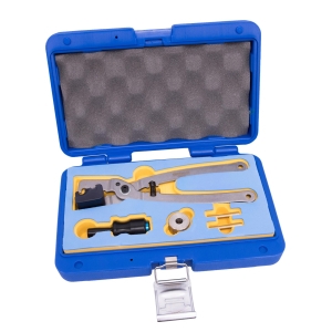
Injector Seal Ring Tool for Gen 2 BMW B36 B38 B46 B48 B58
Price: €199.50Available • 5–10 Days Delivery
-
-
-
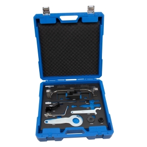
Engine Timing Tool Kit for BMW / Mini B32–B58 Petrol & Hybrid Engines (Timing Chain)
Price: €695.00Temporarily Unavailable
-
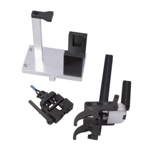
Valvetronic Torsion Spring Tensioning Tool Set for BMW Mini B36 B38 B48 B58, as OEM 2359088 / 2359089
Price: €695.00Temporarily Unavailable