Fuel Injector Puller Set for Opel & GM SGE 3- and 4-Cylinder Direct Injection Engines
-
Code:117686E
-
Weight:12.448 Kgs
Professional special tool set for safe removal of direct fuel injectors together with the fuel rail on Opel and GM SGE petrol engines. Equivalent to OEM EN-51146.
This professional injector extraction kit is specifically designed for the controlled removal of high-pressure direct fuel injectors installed in Opel and GM SGE (Small Gasoline Engine) 3- and 4-cylinder engines.
The tool allows removal of the injectors together with the fuel rail in accordance with manufacturer procedures, minimizing the risk of damage to injectors, high-pressure fuel pipes, and sealing components. Improper removal of high-pressure injection systems can result in fuel leakage, sealing failure, or fire hazard — this tool ensures safe and correct service operation.
Equivalent to OEM reference EN-51146 and related sub-components.
Advantages
-
Enables safe removal of injectors together with the fuel rail
-
Prevents damage to injectors and high-pressure fuel connections
-
Designed for high-pressure direct injection petrol engines
-
Covers all 3- and 4-cylinder Opel/GM SGE engines including:
GM 1.0L LE1, 1.4L LE2, LFE, LV7 and 1.6L LWC
Vehicle Compatibility
Models:
Adam, Astra K, Astra J, Cascada, Corsa E, Insignia B, Meriva B, Mokka, Mokka X, Zafira, Orlando
Engine Codes:
A16XHT, B10XE, B10XFL, B10XFT, B10XL, B14XFL, B14XFT, B14XNT, B15SFL, B15SFT, B16SHL, D14XFL, D14XFT, D14XNT, D15SFL, D15SFLFT, F16SFLFT, F15SFL
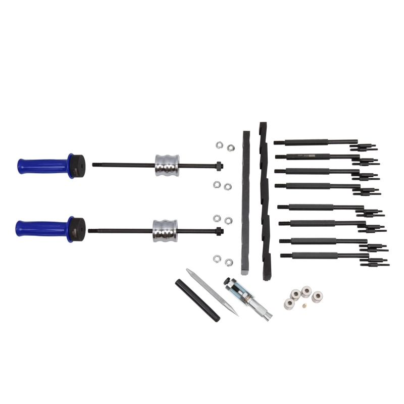
Kit Contents
-
Extraction Bolt 120627 – equivalent to EN51146-1-6 (for Continental/VDO injectors)
-
Extraction Bolt 120629 – equivalent to EN51146-150 (for Bosch injectors)
-
Adapter Plate 116743 – equivalent to EN51146-100 (for SGE 1.0L & 1.4L engines)
-
Adapter Plate 120626 – equivalent to EN51146-1-2 (for SIDI 1.4L & 1.6L engines)
Important Safety Information
⚠ The fuel rail operates under high pressure.
Incorrect disassembly may cause fuel leakage and risk of engine fire.
Always follow the manufacturer’s prescribed depressurization and removal procedure.
Application Procedure
-
Remove ignition coils.
-
Loosen fuel rail mounting bolts.
-
Replace original bolts with extraction bolts and tighten to 5 Nm.
-
Remove fuel rail and injectors as one assembly.
-
Use the puller and adapter plate to extract injectors safely.
-
Replace injector sealing rings using proper calibration and installation sleeves.
Seal Replacement
Use correct calibration tools and installation sleeves to ensure proper sealing and prevent injector damage.
OEM Reference
EN51146
EN-51146-100
EN-51146-150
Original numbers are for comparison purposes only. This is not an original OEM tool.
Procedure
(WARNING: Do not remove the fuel injectors from the fuel rail unless absolutely necessary.)
Removal
-
Remove the ignition coils.
-
Loosen the 6 bolts securing the fuel rail (do not remove them yet).
-
Remove one injector retaining bolt at a time and immediately replace it with the pre-assembled extraction stud (120627 with 120628 or 120629). Tighten to 5 Nm.
-
Repeat this procedure for all 6 or 8 bolts, depending on engine configuration.
-
-
Fully remove all 6 fuel rail bolts and the 3 or 4 injector bolts.
-
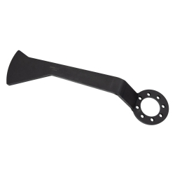
Install the extraction plate (depending on engine: 120626 or 116743) with the arrow pointing in the direction of travel.
-
Ensure the correct angle is maintained and check whether the second plate is required.
-
-
Install and tighten the serrated nuts.
-
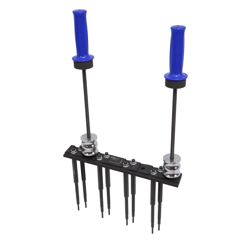
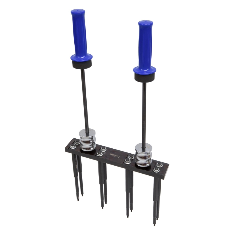
Insert the guide rods (117440) and lock them in place.
-
Mount the sliding weights (115174) and handles (115175).
-
-
With a second technician, pull evenly upward on the handles while applying impact force with the sliding weight to extract the assembly.
-
The bridge assembly can be clamped in a bench vise using the plate in order to replace the sealing rings.
Replacing the Sealing Rings
-
The calibration tools / compression sleeves (106387) are also used to protect the injectors.
They maintain the sealing rings at installation size until reinstallation.
-
Inspect all injectors for damage.
-
Using pin tool 120630, remove the two combustion chamber seals from each injector.
-
Use only this pin tool. Do not use metal tools as substitutes.
-
Pierce the seal with the pin and tear it open for removal.
-
-
Install the new sealing rings one at a time:
-
Slide each seal onto the injector using the installation cone.
-
Press it over the injector using the plastic installation sleeve (slotted side facing forward).
-
Start with the rear sealing ring using the long installation cone (121593).
-
Then install the front sealing ring using the shorter cone (106397).
-
Calibration / Compression of the Sealing Rings
After installing both sealing rings, they must be compressed (calibrated).
-
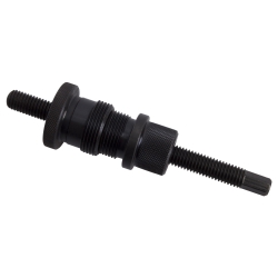
Use calibration tool 120632.
-
The attached puller with the external hex screw is used ONLY to loosen the puller’s union sleeve.
-
If the compression tool can be loosened by hand, the puller is not required.
-
-
To calibrate both sealing rings simultaneously:
-
Fully open the tool and slide it over the injector until the internal Teflon sleeve covers both sealing rings.
-
-
Hold the opposite end of the tool with a wrench and tighten the nut.
-
The union sleeve compresses the segments and thereby the sealing rings.
-
-
Perform this process slowly and evenly until:
-
The jaws are fully closed AND/OR
-
Only 4.5 mm of the jaws remain visible.
-
-
Loosen the nut of the tool.
-
If the union sleeve cannot be retracted by hand, do not use other tools — use the puller.
-
-
Inspect the sealing rings.
-
Using a twisting motion, slide the compression sleeves over the injector.
-
Remove the sleeves and inspect the sealing rings again.
-
Reinstall the compression sleeves and leave them in place until final installation.
| Item | Quantity | Product Description |
|---|---|---|
| 120626 | 1 pc | Base plate short, to be used as EN-51146-1-2 |
| 120627 | 8 pcs | Pull stud with nuts, to be used as EN-51146-1-1 |
| 120628 | 16 pcs | Adapter bolt, to be used as EN-51146-1-6 |
| 120629 | 8 pcs | Adapter bolt, to be used as EN-51146-150 |
| 120630 | 1 pc | Pin for removing sealing rings, to be used as EN-51146-2-1 |
| 120631 | 1 pc | Seal ring installation sleeve, to be used as EN-51146-2-6-1 |
| 120632 | 1 pc | Seal ring calibration tool, to be used as EN-51146-2-4 |
| 116743 | 1 pc | Base plate long, to be used as EN-51146-100 |
| 106387 | 4 pcs | Compression sleeve for sealing ring, to be used as EN-51146-2-5 |
| 121593 | 1 pc | Seal ring installation cone, as EN-51146-2-2 |
| 106397 | 1 pc | Seal ring installation cone, to be used as EN-51146-2-2 / -3 |
| 115174 | 2 pcs | Slide hammer weight, to be used as EN-51146-1-3 |
| 115175 | 2 pcs | Slide hammer handle, to be used as EN-51146-1-3 |
| 117440 | 2 pcs | Slide hammer guide rod, to be used as EN-51146-1-3 |
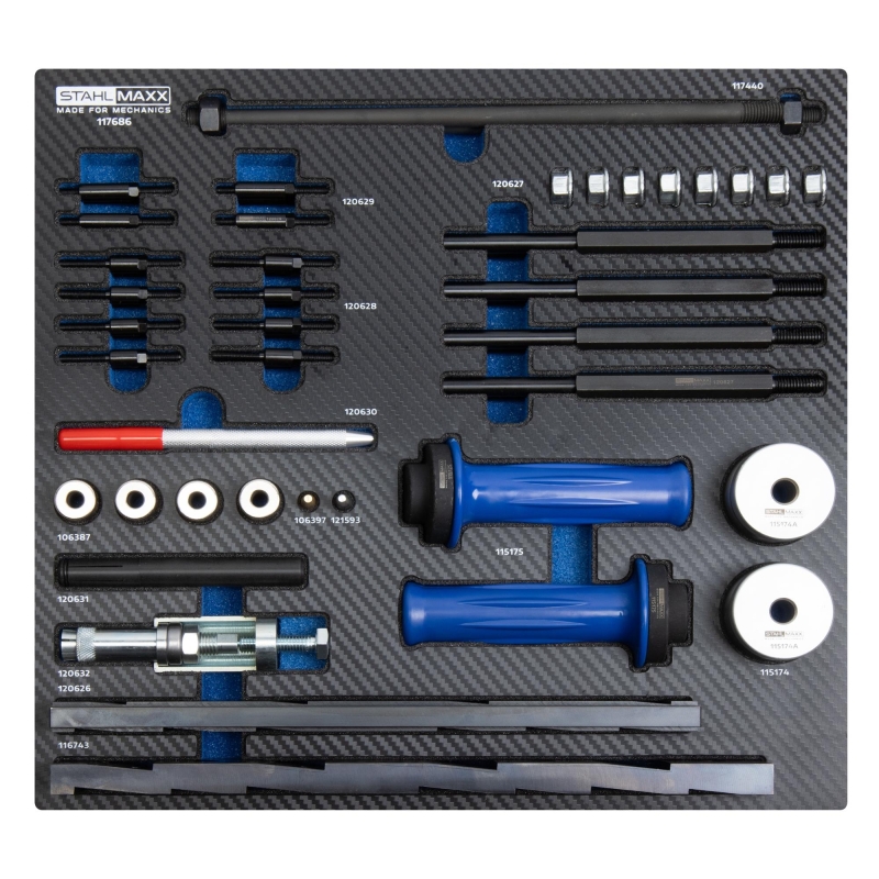
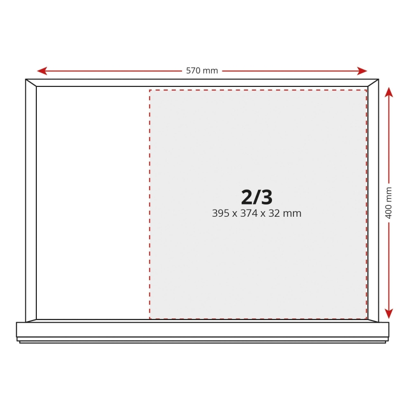
| 117686S | 1 pc | Custom-fit foam insert 2/3 [395 x 374 x 32 mm (L x W x H)] |
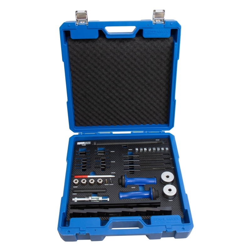
| 122802 | 1 pc | Heavy-duty storage case 2/3 |
OEM numbers are for comparison purposes only. This is not an original manufacturer tool.
-
Opel Injector Installation Tool – Gen 2 Direct Injection Engines
Price: €11.50 22.49лв.In Stock (69 pcs)