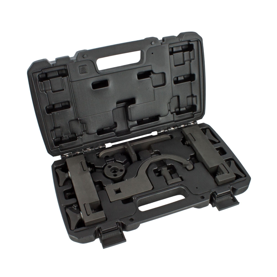
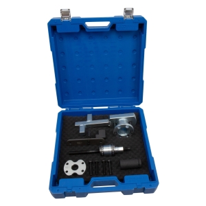
Engine Timing Tool Kit for Jaguar Land Rover V6 & V8 3.0L / 5.0L – AJ126, AJ133 Engines
-
Code:101181
-
Weight:4.500 Kgs
Overview:
✔ Professional engine timing tool kit for Jaguar & Land Rover V6/V8 engines
✔ Suitable for 3.0L and 5.0L petrol engines (AJ126, AJ133 series)
✔ Ensures precise camshaft and crankshaft alignment
✔ Designed for timing chain adjustment and engine service
✔ Compatible with multiple OEM tool references
✔ Ideal for professional workshop use
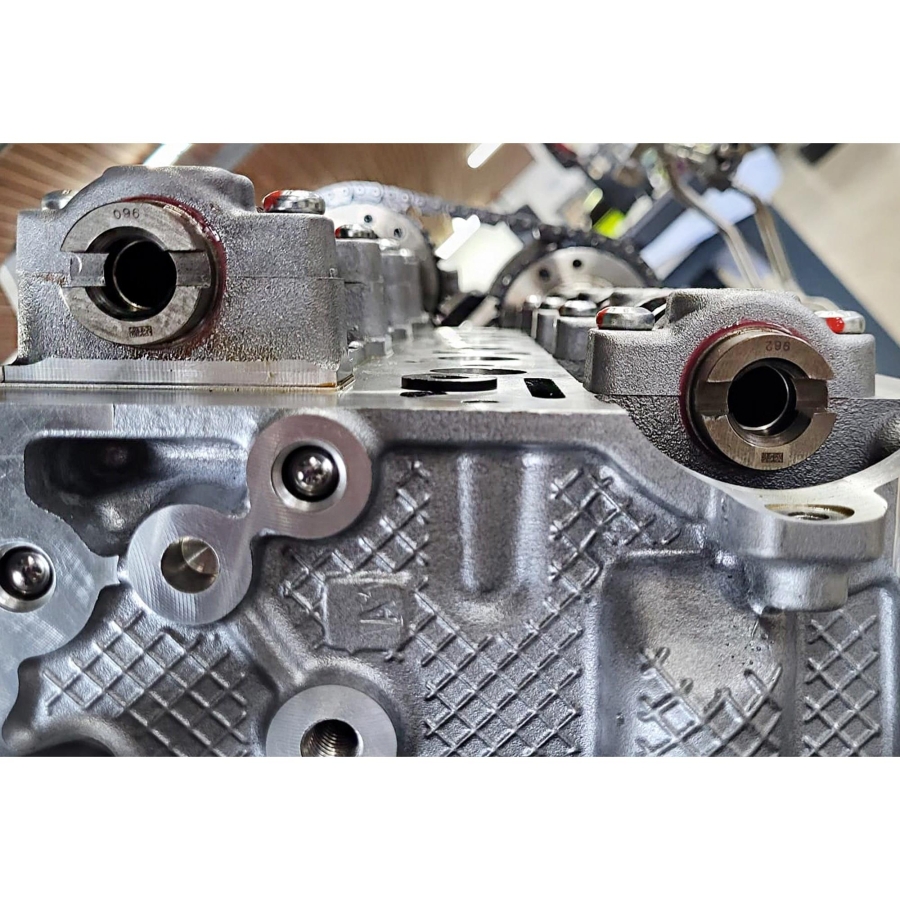
This engine timing tool kit is designed for precise adjustment and locking of the timing chain system on Jaguar and Land Rover V6 and V8 petrol engines. It enables accurate positioning of camshafts and crankshaft during timing service, ensuring correct engine synchronization.
Vehicle Compatibility
Jaguar:
XK8 (X150), XKR (X150), XF / XFR (X250), XJ / XJR (X351), F-Type (X152)
Land Rover:
Discovery 4, Range Rover, Range Rover Sport
Engine Compatibility
✔ AJ126 / 306PS*
✔ AJ133 / 508PS
✔ AJ133G2
✔ AJ133S
✔ AJ133 / 508PN
✔ 306PS*, 508PS, 508PN
Note: Engines marked with * require additional tool item no. 121600 (used as JLR-303-1303), not included in the set.*
Functions
✔ Locks camshafts in correct timing position
✔ Secures crankshaft during service operations
✔ Assists in timing chain installation and adjustment
✔ Prevents engine misalignment during maintenance
Included Tools
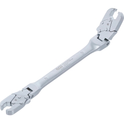
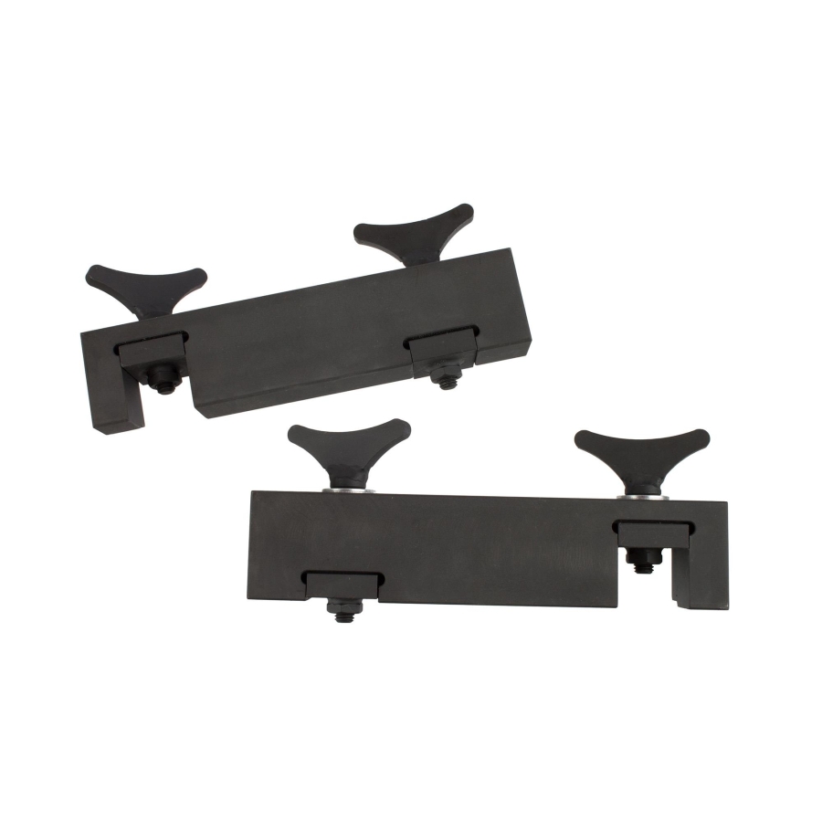
✔ Camshaft alignment tool set – used as 303-1445
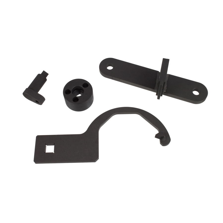
✔ Crankshaft setting tool – used as 303-1447
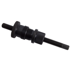
✔ Camshaft turning tool – used as 303-1452
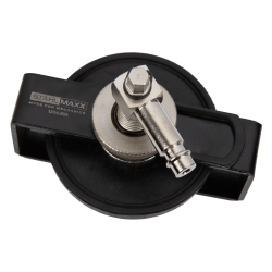
✔ Timing chain tensioner – used as 303-1482
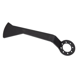
✔ Flywheel holding tool (starter opening) – used as 303-1448
OEM numbers are provided for reference only. This product is not an original manufacturer tool.
REMOVAL
Warning: Engines with variable valve timing: Before removal or disassembly, mark the camshafts, camshaft sprockets, camshaft adjusters, and associated camshaft drive components (if applicable) using chalk or paint to facilitate correct alignment during installation.
- Remove the crankshaft position sensor (CKP sensor).
- Rotate the crankshaft in the engine’s direction of rotation until the crankshaft locking pin can be installed.
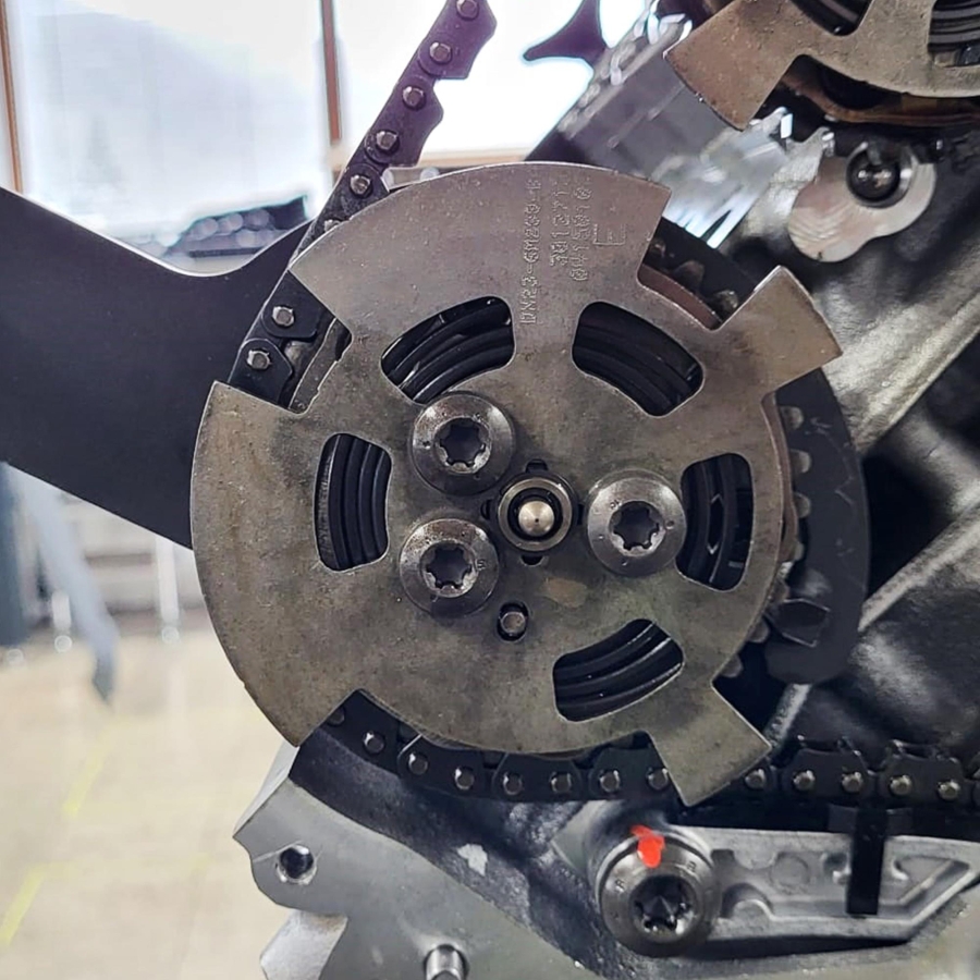
- Ensure that the notch on the crankshaft sprocket is in the 6 o’clock position.
Note: Replace the drive plate if the notch on the crankshaft sprocket is in the 9 o’clock position. - Ensure that the groove on the rear of the camshafts is positioned as shown.
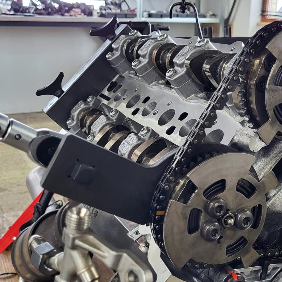
- Remove both the timing chain tensioner and the tensioning rail from the right cylinder bank.
- Loosen the bolts on each camshaft adjuster of the right cylinder bank.
- Remove both the camshaft adjusters and the timing chain from the right cylinder bank.
- Remove both the timing chain tensioner and the tensioning rail from the left cylinder bank.
- Loosen the bolts on each camshaft adjuster of the left cylinder bank.
- Remove both the camshaft adjusters and the timing chain from the left cylinder bank.
Note: Crankshaft sprocket friction washers MUST be replaced.
INSTALLATION (Part 1)
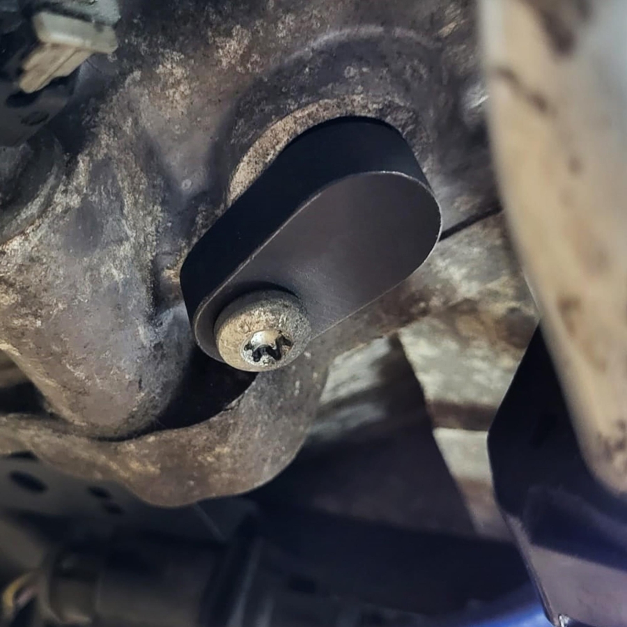
- Ensure that the crankshaft locking pin is correctly installed.
- Ensure that the notch on the crankshaft sprocket is in the 6 o’clock position.
- Ensure that the groove on the rear of the camshafts is positioned as shown.
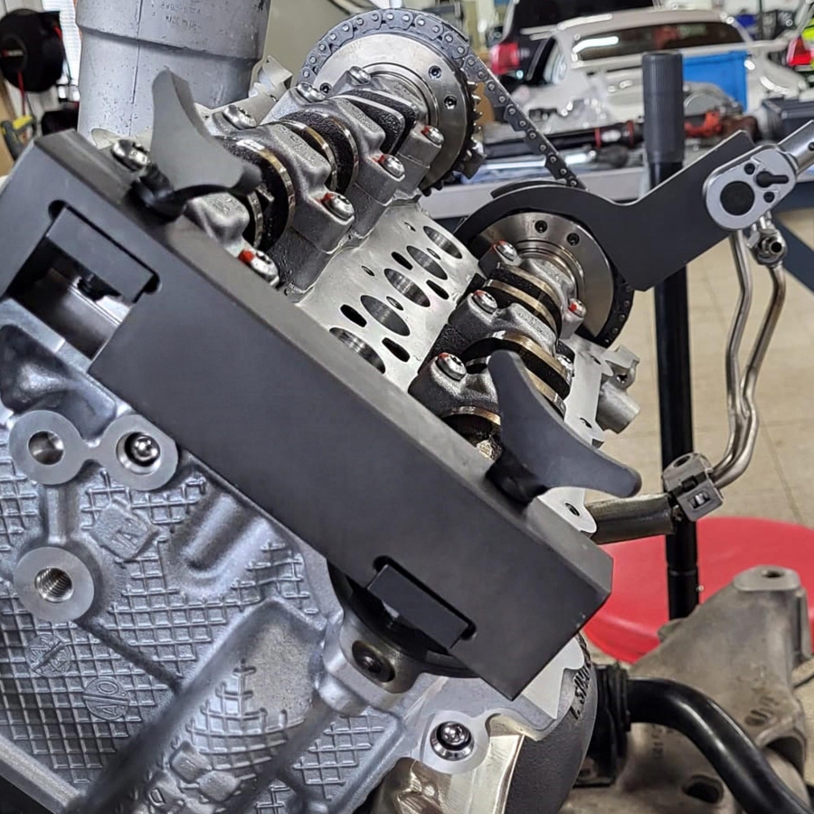
- Attach the camshaft turning tools to the front of the camshafts on the left cylinder bank.
- Attach the camshaft alignment tool to the rear of the camshafts on the left cylinder bank.
- Ensure that the camshaft alignment tool engages at the end of the camshafts. Secure the tool with bolts and tighten them hand-tight.
- Slightly move the camshafts to ensure the alignment tool is correctly positioned.
- Remove the camshaft turning tools.
- Attach the camshaft turning tools to the front of the camshafts on the right cylinder bank.
- Attach the camshaft alignment tool to the rear of the camshafts on the right cylinder bank.
- Ensure that the camshaft alignment tool engages at the end of the camshafts. Secure the tool with bolts and tighten them hand-tight.
- Slightly move the camshafts to ensure the alignment tool is correctly positioned.
- Lock the timing chain tensioners of both the left and right cylinder banks in the retracted position.
Note: There are two types of tensioners:
- Tensioner – Type A:
- Push the piston into the tensioner housing in the direction of the arrow.
- Insert a suitable pin into the housing to lock the piston in position.
INSTALLATION (Part 2)
- Tensioner – Type B:
- Turn the locking pawl fully clockwise.
- Push the piston into the tensioner housing in the direction of the arrow.
- Turn the locking pawl fully counterclockwise.
- Insert a suitable pin into the housing to lock the piston in position.
- Install the camshaft adjusters and timing chain on the left cylinder bank as an assembly. Tighten the bolts hand-tight.
- Ensure that the colored/painted chain links align with the marks on each camshaft adjuster and each chain guide.
- Install both the timing chain tensioner and the tensioning rail on the left cylinder bank.
- Install the camshaft adjusters and timing chain on the right cylinder bank as an assembly. Tighten the bolts hand-tight.
- Ensure that the colored/painted chain links align with the marks on each camshaft adjuster and each chain guide.
- Install both the timing chain tensioner and the tensioning rail on the right cylinder bank.
- Remove the pin to release the timing chain tensioner piston.
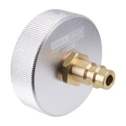
- Attach the timing chain pre-tensioning tool to the intake camshaft adjuster of the left cylinder bank.
- Apply a pre-tension torque of 35 Nm.
- Tighten the adjustment bolts of the exhaust camshaft on the left cylinder bank.
Tightening torque: 32 Nm. - Tighten the adjustment bolts of the intake camshaft on the left cylinder bank.
Tightening torque: 32 Nm. - Remove the timing chain pre-tensioning tool.
- Attach the timing chain pre-tensioning tool to the exhaust camshaft adjuster of the right cylinder bank.
- Apply a pre-tension torque of 35 Nm.
- Tighten the adjustment bolts of the intake camshaft on the right cylinder bank.
Tightening torque: 32 Nm. - Tighten the adjustment bolts of the exhaust camshaft on the right cylinder bank.
Tightening torque: 32 Nm. - Remove the timing chain pre-tensioning tool.
- Remove the camshaft alignment tools.
- Remove the crankshaft locking pin.
- Install the flywheel locking tool.
- Temporarily install the crankshaft pulley bolt with an M16 washer.
Tightening torque: 50 Nm. - Remove the flywheel locking tool.
- Rotate the crankshaft two full turns clockwise.
- Install the flywheel locking tool.
- Remove the crankshaft locking pin.
- Remove the flywheel locking tool.
- Rotate the crankshaft in the engine’s direction of rotation until the crankshaft locking pin can be installed.
- Ensure that the camshaft alignment tools can be installed. If not, repeat the timing chain installation procedure.
- Remove the camshaft alignment tools.
- Remove the crankshaft locking pin.
- There are two types of crankshaft pulley bolts:
- Strength class 10.9 (right-hand thread)
- Strength class 12.9 (left-hand thread)
- Tighten the crankshaft pulley bolt. Always use a new bolt.
Tightening torque: 200 Nm + 270°
-
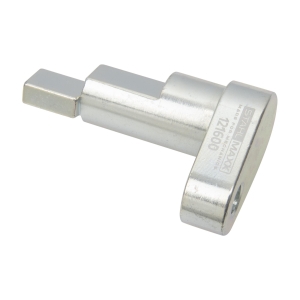
Crankshaft Locking Pin for Jaguar / Land Rover AJ126, AJ133 (as JLR-303-1303)
Price: €36.95 72.27лв.In Stock (16 pcs)
-
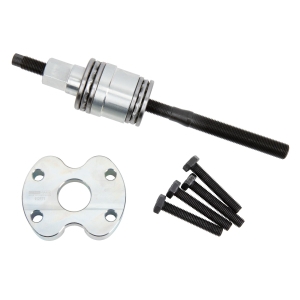
Crankshaft Pulley Puller Tool Set for Jaguar / Land Rover (as 303-1439, 303-1440, 303-1441)
Price: €114.95 224.82лв.In Stock (13 pcs)
-
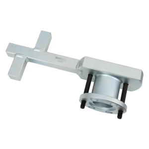
Crankshaft Holding Tool for Jaguar / Land Rover V6 & V8 (as 303-1437)
Price: €255.00 498.74лв.In Stock (5 pcs)
-
Crankshaft Holding & Pulley Puller Tool Set for Jaguar / Land Rover 3.5L–5.0L (as 303-1304, 303-1437, 303-1439, 303-1440, 303-1441, 303-1448)
Price: €489.00 956.40лв.In Stock (1 pcs)
-
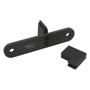
Flywheel Locking Tool for Jaguar / Land Rover 3.0L & 5.0L (as 303-1304, 303-1448)
Price: €88.50 173.09лв.In Stock (32 pcs)