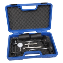
DSG Dual Clutch Transmission Tool Set for VAG VW Audi, for DQ200, 0AM, 08D
-
Code:116568
-
Weight:5.780 Kgs
Overview:
✔ Professional DSG clutch service tool set for VAG transmissions
✔ Suitable for 6-speed and 7-speed direct shift gearboxes
✔ Designed for installation and removal of DSG clutch packs
✔ Compatible with DQ200, 0AM, 08D and related transmissions
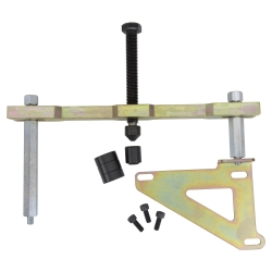
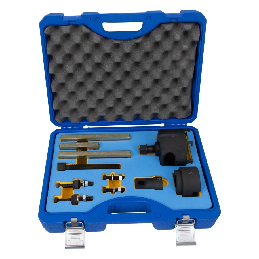
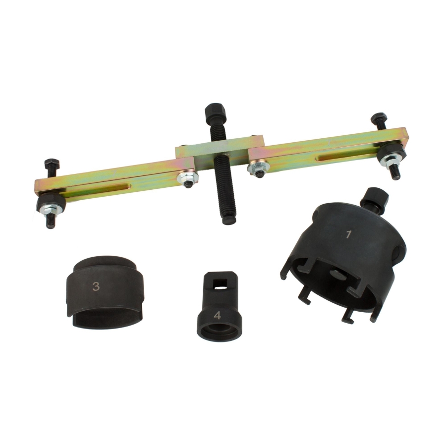
✔ Includes support bridge, puller, measuring gauge, and pressure adapter
✔ Suitable for Audi and Volkswagen DSG transmission service
✔ Designed for professional workshop applications
✔ item no. compatible references: as T10323, T10373, T10374, T10376
Specialized tool set designed for the installation and removal of DSG clutch assemblies and clutch packs used in VAG 6-speed and 7-speed direct shift transmissions.
The set is suitable for professional servicing and repair of DSG transmissions installed in Audi and Volkswagen vehicles. It enables controlled clutch removal, installation, and clutch measurement procedures during transmission repairs.
Compatible with transmission codes such as DQ200, 0AM, 08D, and related DSG gearbox variants.
Compatible Transmission Codes
- DQ200
- 0AM
- 08D
Compatible Vehicles
- VW Golf (from 2004), Golf Plus (from 2005) with 7-speed transmission
- Audi A3 (from 2004) with 7-speed transmission
- VW Touareg (from 2003) with 6-speed transmission
Reference Numbers
To be used as:
- T10323
- T10373
- T10374
- T10376
Package Contents
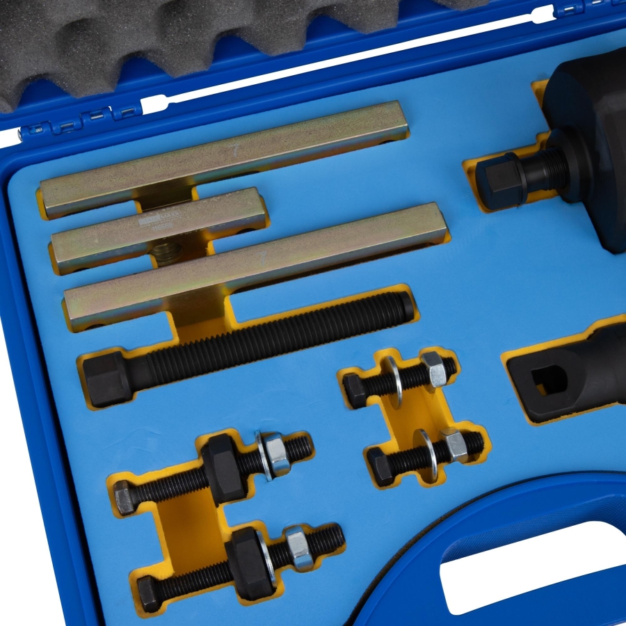
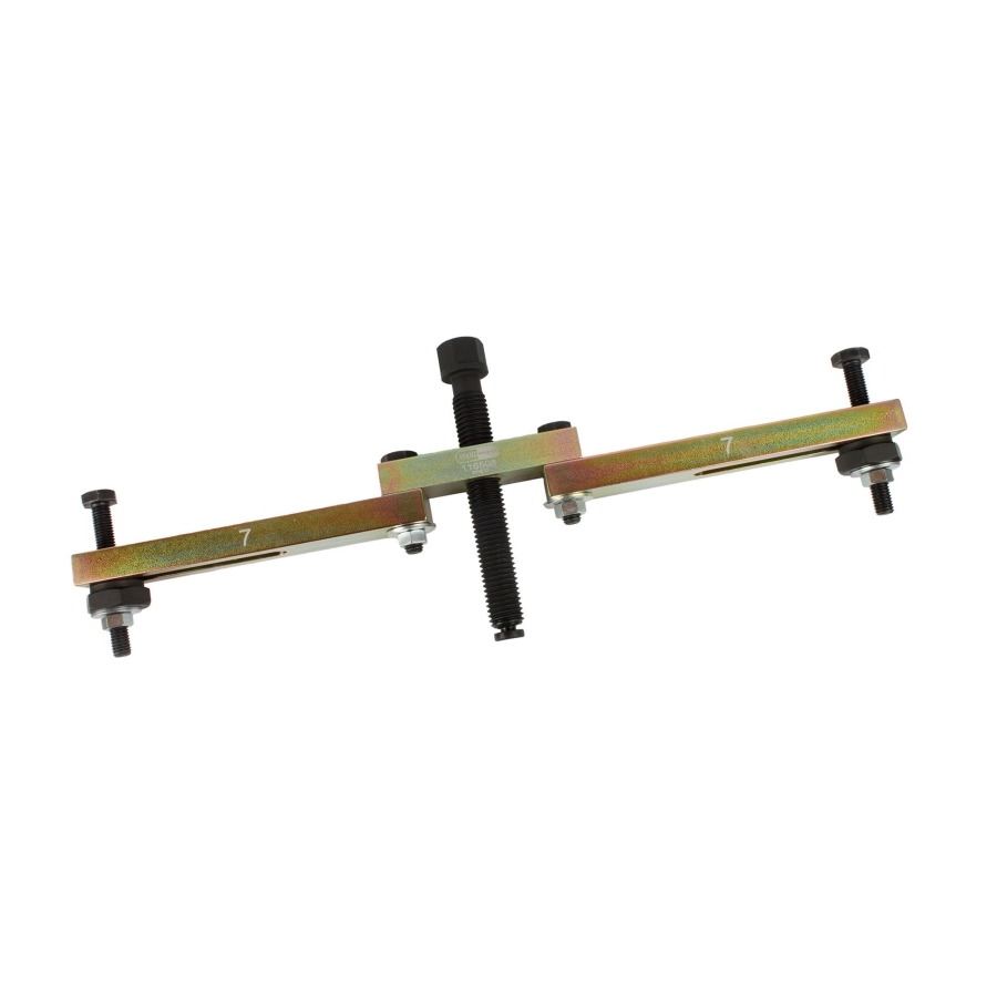
- Support bridge, to be used as OEM T10323
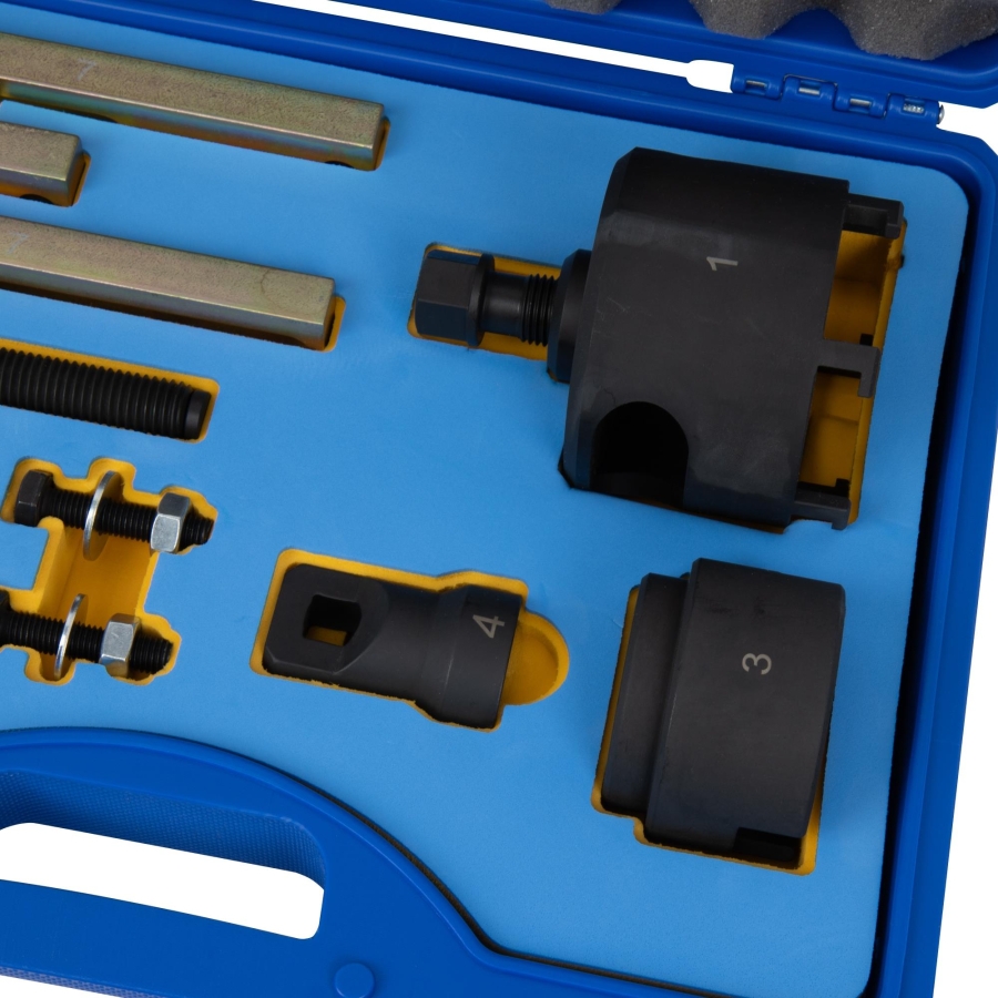
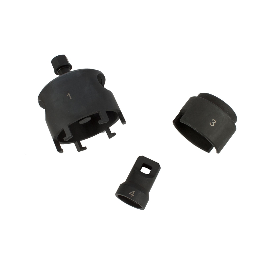
- Puller, to be used as OEM T10373
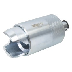
- Measuring gauge, to be used as OEM T10374
- Suitable for measuring both clutch assemblies
- Can be used on both sides
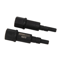
- Pressure adapter, to be used as OEM T10376
Important Information
For model years / transmission production dates from 06.2011 onward, an updated measuring gauge for clutch adjustment K1 and K2 is required.
Use measuring gauge as OEM T10466, see item no. 116569.
An operating manual is included with the tool set. Always follow OEM procedures or equivalent workshop documentation during service operations.
Original numbers are used for comparison purposes only. This is not an original manufacturer tool.
ATTENTION:
- From model year or gearbox production date 06/2011 onwards, a modified final dimension gauge – to be used as OEM tool T10466 – is required for clutch adjustment. See Article No. 116569.
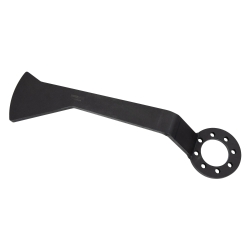
(Modified work instructions, see supplement Article No. 116569 or manufacturer documentation.) - For removal, we recommend using the extraction hook Article No. 43022, equivalent to VW3438.
- Measuring tools such as a depth gauge caliper (up to 300 mm) and a straight edge must be available.
- If the same components are reinstalled, no adjustment is required.
- If the dual clutch is replaced, both release levers with release bearings, their support brackets, and the adjustment shims must also be replaced.
- When reinstalling the original parts, only replace the retaining ring.
- Ensure that no oil leaks from the mechatronic unit (seal the ventilation openings).
Removal:
- Remove the gearbox and, if necessary, mount it on an assembly stand equivalent to VW309 / VW353.
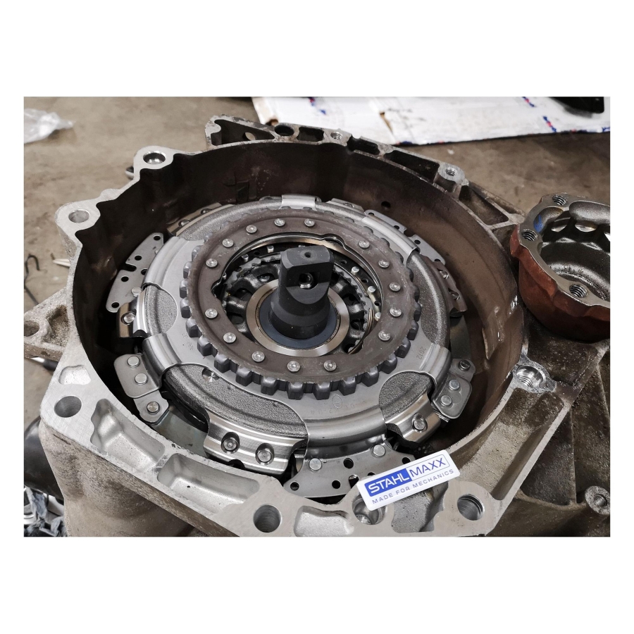
- Remove the retaining ring around the hub with the torsion springs and carefully pry out the hub.
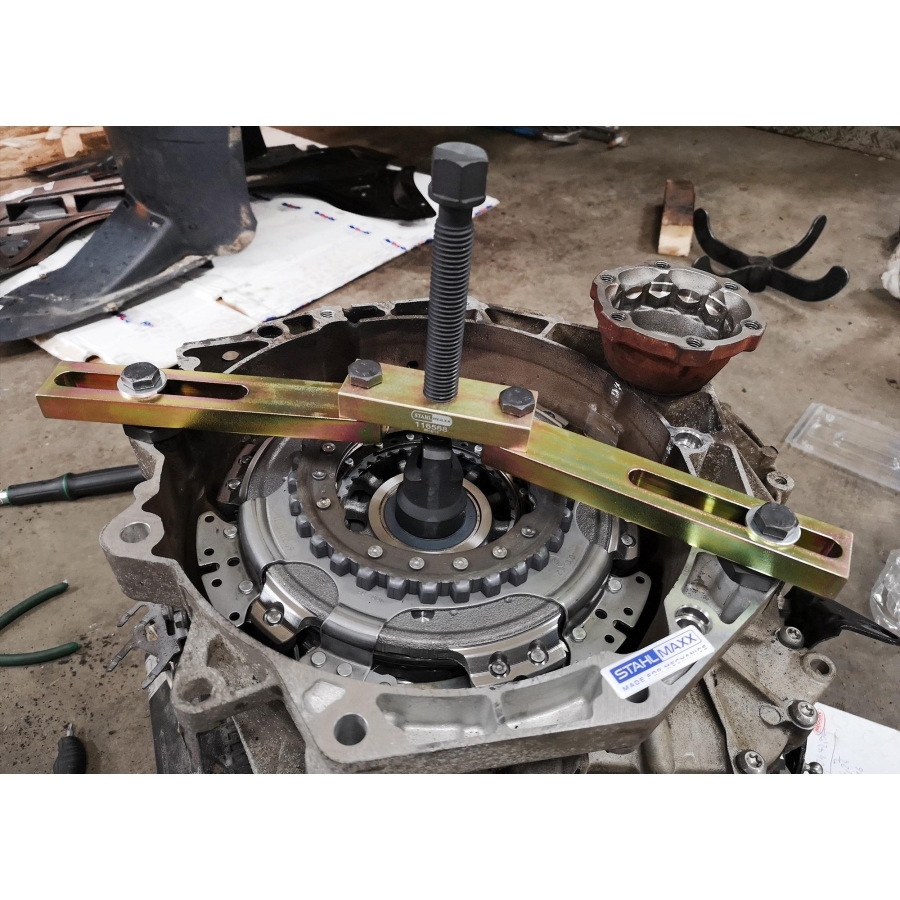
- Remove the retaining ring around the shaft. If necessary, use support bridge 5/6/7/8 and pressure piece 4 to press the clutch downward in order to relieve tension on the retaining ring.
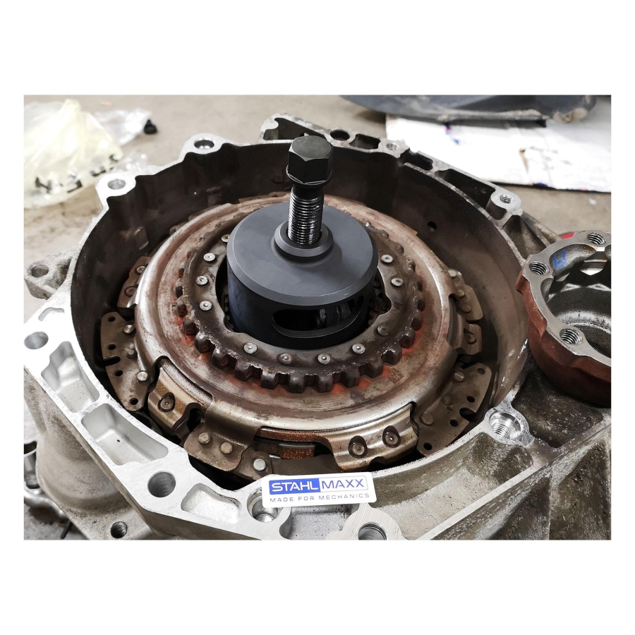
- Install puller 1 and use screw 2 to press out and remove the clutch assembly.
- Remove the small release bearing and the large release lever.
- Remove the two small screws and take out the small release lever with bracket.
- Remove the support bracket for the release lever.
Installation:
- Clean the gearbox bell housing and mounting points from dust and grease.
- Install the support bracket for the release lever.
- Install the small release lever with bracket and tighten the two small screws to 8 Nm + 90° (replace screws).
- Install the large release lever and check the seating of both levers.
- Install the old retaining ring onto the outer shaft.
Always follow the vehicle manufacturer’s repair instructions and torque specifications.
Measuring the Clutch:
1. Determine dimension B – record the measured values in the table
- Place the straight edge vertically across the housing and keep it in position.
- Position the depth gauge caliper on the straight edge and measure the difference between the top edge of the shaft and the retaining ring (dimension B1).
- Repeat the procedure on the opposite side (dimension B2).
- Calculate the average value:
(B1 + B2) / 2 = B
2. Determine dimension A1 (A1 = Clutch 1)
(Install the large release lever with the large release bearing.)
- Position the measuring gauge onto the large release bearing with the flat side facing upward.
To verify correct seating, rotate the gauge by hand under slight pressure. The release bearing should rotate together with the gauge. - Position the depth gauge caliper on the straight edge and measure the difference between the top edge of the shaft and the surface of the measuring gauge (dimension A1a).
- Repeat the procedure on the opposite side (dimension A1b).
- Calculate the average value:
(A1a + A1b) / 2 = A1
3. Calculate the installation depth of release bearing K1 (dimension K1)
- The value 51.81 mm is a fixed value representing the height of the measuring gauge.
4. Determine clutch clearance K1 (dimension LK1)
- The value 50.08 mm is a fixed value.
5. Determine clutch tolerance
- Read the clutch tolerance value
(e.g. Kt1 +0.2; Kt2 -0.2).
Example: Kt1 = +0.2
6. Determine adjustment shim thickness SK1
- Select the appropriate adjustment shim (see table below) and mark it as SK1.
7. Determine dimension A2 (A2 = Clutch 2)
- Attention: Install only the small release bearing! Verify correct seating.
- Position the measuring gauge with the large opening facing upward onto the small release bearing.
- Position the depth gauge caliper on the straight edge and measure the difference between the top edge of the shaft and the surface of the measuring gauge (not the edge) – dimension A2a.
- Repeat the procedure on the opposite side (dimension A2b).
- Calculate the average value:
(A2a + A2b) / 2 = A2
8. Calculate the installation depth of release bearing K2 (dimension K2)
- The value 36.20 mm is a fixed value representing the height of the measuring gauge.
9. Determine clutch clearance K2 (dimension LK2)
- The value 34.35 mm is a fixed value.
10. Determine clutch tolerance
- Read the clutch tolerance value
(e.g. Kt1 +0.2; Kt2 -0.2).
Example: Kt2 = -0.2
11. Determine adjustment shim thickness SK2
- Select the appropriate adjustment shim (see table below) and mark it as SK2.
12. Adjustment procedure completed
ATTENTION:
The clutch may only be installed if the adjustment has been carried out correctly!
| Measured Adjustment Shim Thickness (mm) | Available Adjustment Shim Thickness (mm) |
|---|---|
| 0.31 – 0.90 | 0.80 |
| 0.91 – 1.10 | 1.00 |
| 1.11 – 1.30 | 1.20 |
| 1.31 – 1.50 | 1.40 |
| 1.51 – 1.70 | 1.60 |
| 1.71 – 1.90 | 1.80 |
| 1.91 – 2.10 | 2.00 |
| 2.11 – 2.30 | 2.20 |
| 2.31 – 2.50 | 2.40 |
| 2.51 – 2.70 | 2.60 |
| 2.71 – 3.30 | 2.80 |
Installing the Clutch:
- The small release lever is already installed.
- Install the large release lever and check correct seating.
- Insert adjustment shim SK2 underneath the small release bearing, install the bearing, and verify correct seating.
- Secure the large adjustment shim SK1 onto the large release bearing using 3 small drops of adhesive (do not use grease!) to prevent the shim from moving during clutch installation.
- Lock puller 1 into the clutch and install the clutch together with the puller.
- Mount the support bridge with the pressure piece straight onto the housing and press the clutch downward.
(Place one hand on the clutch to feel the stop point; slight rattling is normal.) - Install the retaining ring (narrow gap facing upward).
- To establish the operating position, install puller 1 and press the clutch by hand firmly against the retaining ring.
- Install the hub (observe installation direction – the large tooth).
- Install the hub retaining ring and verify correct seating.
- Move the clutch back and forth by hand while observing the release lever – the lever must not move.
- After installation, perform the “Basic Setting” procedure using a diagnostic tester under “Guided Functions”.
Always follow the vehicle manufacturer’s repair instructions and torque specifications.